


A New Engine-operated Tipping Gear
Page 75
If you've noticed an error in this article please click here to report it so we can fix it.
TrISITORS to the Commercial Motor V Show at Olympia last week must have noticed on the Vulcan stand a 30-cwt. chassis equipped with an endtipping body operated by a mechanism which had not been seen before. This tipping gear has been designed and produced by Messrs. Edwards Brothers, of Springfield Garage, Bradford Street, Bolton.
The layout of the driving mechanism is as follows :—The drive is taken by a longitudinal shaft from the gearbox, this shaft carrying a sliding pinion which can be engaged with the constant-mesh wheel. As a matter of fact, -in the ease of the Vulcan 30-cwt. machine, the drive has been taken from the tyre-pump mechanism, but such an arrangement would not be possible on every chassis.
On this shaft there is a metal-tometal cone-type brake, actuated by the same lever as is the sliding gear, so that, as the brake is applied, the pinion is pulled out of mesh. At the rear end of the shaft the power is transmitted from a 12-toothed sprocket by a roller chain -to a 34-toothed sprocket and further reduction is obtained by a seeond chain, another! 12-toothed sprocket, driving another 34-toothed sprocket which is mounted on a 'longitudinal worm shaft.
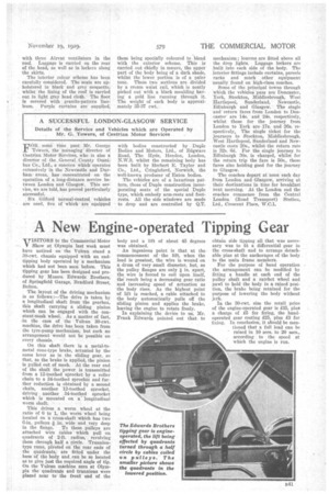
This drives a worm wheel at the ratio of 6 to 1, the worm wheel being located on 'a cross-shaft which has two etin. pulleys 4 in. wide and very deep in the flange.these pulleys are attached wire ables which pull on quadrants of 2-ft. radius, revolving them through half a circle. Trunniontype rams, pivoted on the rear ends of the qUadrants, ate fitted under the base of the body and, can be so located as to give just the required angle of tip. On the Vulcan machine seen at Olympia the quadrants and trunnions were placed near to the front end of the
body and a lift of about 45 degrees was obtained.
An ingenious point is that at the commencement of the lift, when the load is greatest, the wire is wound on a drum of very small diameter, but, as the pulley flanges are only in. apart, the wire is forced to coil upon itself, the result being a decreasing gear ratio and increasing speed of actuation as the body rises. As the highest point of lift is reached, a cable 'attached to the body automatically pulls off the sliding pinion and applies the brake, leaving the engine to rotate freely.
In explaining the device to us, Mr. Frank Edwards pointed out that to obtain side tipping all that was necessary was to fit a differential gear in the cross-shaft and to arrange detachable pins at the anchorages of the body to the main frame members.
For the purpose of hand operation the arrangement can be modified by fitting a handle at each end of the pulley shaft and a ratchet wheel and pawl to hold the body in a raised position, the brake being retained for the purpose of lowering the body without jerk.
In the 30-cwt. size the retail price of the engine-operated gear is £35, plus a charge of £5 for fixing, the handoperated gear costing £25, plus £3 for fixing. In conclusion, it should be mentioned that a full load can be raised in 10 secs. to 20 secs., according to the speed at which the engine is run.