


The Arrival of THE ARROW
Page 48
Page 49
If you've noticed an error in this article please click here to report it so we can fix it.
A New Dennis Low-load-line Six-cylinder Chassis for 32 seater Bodies, which Incorporates Many Novel Features
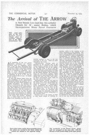
This semi plan view of the new Dennis Arrow chassis gives an excellent impression of the offset transmission line, AN inspection of the new Arrow chassis produced by Dennis Brothers, Ltd., of Guildford, proves that it has not been dispatched upon its mission without very careful thought having been given to the class of service it is intended to undertake. It is built to carry 32-seater single-deck bodies and has a frame height of 2 ft., a wheelbase of 16 ft. 6 ins, and an overall length of 25 ft. 4 ins. It weighs 2 tons 19 cwt.
In plan the chassis tapers from the front dumbirons to the cross-member immediately behind the gearbox; aft of this point the main frame members run parallel throughout. In elevation the frame is down-swept from the front to the rear mounting of the engine-gearbox unit, after which the members are horizontally disposed, with the exception of the portion up-swept to clear the rear axle. One IJ-section and Eve tubular cross-members are employed, in addition to the bridge which carries the rear end of the engine and gearbox. Incidentally, a rubber block is used for the single front mounting, and the same in.
sulating medium is used in the two trunnions at the rear. Bolts are used throughout the frame.
Cam-and-roller steering gear is mounted at the forward end of the frame to give a position for the driver on the right-hand side of the engine. The turning circle is 58 ft. and the swivel heads have taper-roller bearings. In all cases Silentbloe bearings are used for the spring shackles, the suspension being by semi-elliptie springs, which under load are approximately flat. Disc wheels are used, and they carry 38-in. by 81--in, low-pressure tyres, those on the rear wheels being dual.
Interchangeable facings are used on all brake shoes; these are expanded in the drums of all four wheels when the pedal is depressed, a vacuum-servo motor augmenting the driver's effort. The hand lever operates shoes in the rear wheels only. In the case of the front-wheel brakes the operating rods pass through the king-pins, thus making the braking entirely independent of any steering action.
Turning now to the engine, we find a very sound design of striking in
genuity, which is the outcome of 34 years' experience in the industry. The power unit is slightly offset to the near side and inclined to give a straight-line transmission, in elevation and plan. The six cylinders are cast en bloc and have a bore and stroke of 100 tam. by 130 mm. respectively, the maximum output being in excess of 100 b.h.p. The cylinder barrels are of the removable type and make direct contact with the cooling water. Seven main bearings of 3-in, diameter carry the crankshaft.
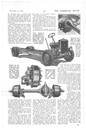
It is in connection with the vidve gear that the most striking novelty is seen. A chain conveys the drive from the crankshaft to the overhead camshaft, an automatic tensioning device being used. The camshaft is disposed on the off side of the engine above the head, and is carried in a trough which forms part of the casing. This casing carries all the rocker gear and is pivoted at its forward end on the rear face of the distribution casing and at the opposite extremity upon a bracket fixed to the cylinder block.
This casing can be swung up and to the right, carrying with it all the rocker gear, so as to clear the cylinder head, which, of course, carries the offset valves and springs. When the rocker casing is vertical the cylinder head can be detached in the usual manner without in any way affecting the drive for
the camshaft; thus, a cylinder head may be taken from stock and substituted for one which needs attention, or the original head may be removed, reconditioned and replaced without any more difficulty than is incurred in performing a similar operation on a sidevalve engine.
Another novel feature is the auxiliary drive. At the front end is a rubber coupling transmitting the drive from the chain distribution gear to the dynamo on, the near side of the engine, after which it passes through the casing, carrying skew gears driving a vertical shaft. Finally, this . auxiliary line drives the magneto. Reverting to the vertical shaft, it is found that the upper end terminates in the spindle of the impeller-type water pump, whilst the lower end drives a submerged oil pump r incidentally, this pump has a separate small feed to the skew gear.
Below the gland of the water pump
is a centrifugal thrower on the shaft to deflect any water which might find its way through the gland, so that it cannotpass into the skew-gear casing ; drainage holes are provided. Both this system of pump drive and the valve mechanism are patented.
A ruStress-steel sleeve is used in the water pump, and the flow of cooling water has been arranged to pass around the sparking-plag bosses, also between the valve packets.
A great deal of interesting detail work is to be found in the engine. For example, the rocker box has a total atnotint of +in. float on its pivots to permit free expansion of the cylinder block and to compensate for different thicknesses of gaskets,etc. The casting is secured by an "ample number of studs
and, when in the normal position, is clamped at the ends. .
The crankcase is carried down 5 ins. below the centre line of the crankshaft, and the lateral ribbing of the case is unusually thoroughly carried out. No fewer than three bearings are used for the fan, which is allowed to rotate on its spindle under the control of friction clutches, during sudden acceleration or deceleration ; an ailless bearing is used for the fan hub.
Automatic chain tension is used for the distribution drive, but slack in the
chain being gradually taken up would cause a slight disturbance of the valve timing; therefore, a worm-adjusting mechanism is built into the driven sprocket on the front of the camshaft to permit variation of the relative positions of the sprocket and the shaft.
Another clever. detail is the. use of a finger in the rocker casting, which, in conjunction with a mark scribed on part of the camshaft, is used to check the correct position of the shaft prior to adjustment of the rockers.
Lubrication is by oil under pressure from the submerged pump to an AutoKlean filter, which has its plater automatically cleaned every time the clutch pedal is depressed... After the filter the oil travels through a drilled passage to a gallery, pipe, which feeds the seven
main bearings ; it passes through steel tubes fixed into the crank webs to the big-end bearings, which have 2f in. journals. Oil emerges from a hole in the driving sprocket on the forward end of the crankshaft and feeds the chain.
The camshaft is lubricated by the following method: Oil passes up through a pipe in the cylinder block to a hollow screw passing through the cylinder head. It then runs into the large centre mounting of the rocker shaft, feeds the rockers and the surplus runs into the camshaft trough. Any overflow is carried away by a vertical passage at the back end of the cylinder block.
No fewer than 15 springs are used in the single dry-plate clutch, which is provided with a stop.
In addition to automatic lubrication of the clutch-centre bearing manual oil feed can be
• applied. All selectors are removable from the side of the gearbox, which also has a dip-stick checking the oil level. A takeoff is provided for a mechanical tyre pump. The gear selectors are controlled by a single operating shaft • connected to the gear lever beside the driver. There are four forward speeds, these being : Top, direct ; third, 7.69 to I; second, 2.79 to 1; first, 5.32 to 1. Aft of the gearbox is a two-piece propeller shaft, with the steady bearing carried in a spherical housing, which is
rubber mounted. A forged-steel axle casing, with an inverted pot offset to the near side, carries the worm gear, with which it gives a ratio of 51 to 1. The shafts are of the semi-floating type.
On the off side of the frame is a 40 gallon fug tank. The priee of this chassis is i1.100.•