


Easy-to-fit Chassis Lubricator
Page 40
If you've noticed an error in this article please click here to report it so we can fix it.
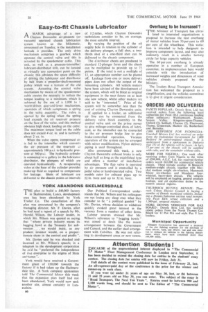
AA MAJOR advantage of a new Clayton Dewandre air-pressure (or vacuum) operated chassis lubrication system known as the Milomatic, announced on Tuesday, is the installation latitude it provides. The only drive mechanism comprises a gearbox which operates the control valve and this is actuated by the speedometer cable. This unit, as well as a pressure-intensifier/ lubricant-distributor unit, can be located at virtually any convenient point on the chassis; this obviates the space difficulty of driving the lubricator and distributor by belt from a propeller-shaft-mounted pulley which was a feature of the old system. Actuating the control valve mechanism by means of the speedometer cable creates the necessity to reduce the torque loading to a minimum, which is achieved by the use of a 1,000 to 1 worm-driven gear-and-lever mechanism, operation of which compresses a spring in the valve assembly. The valve is opened by the spring when the spring load exceeds the air reservoir pressure on the face of the valve, and this method obviates high shock loading on the cable. The maximum torque load on the cable does not exceed 4 oz. in. and is normally about 2 oz. in. When the valve opens, compressed air is fed to the intensifier whIch converts the air pressure of the reservoir at approximately 100 p.s.i. to hydraulic pressure at 500 p.s.i. The hydraulic cylinder is connected to a gallery in the lubricator distributor, the plungers of which are operated hydraulically. A recuperating valve at the base of the cylinder provides make-up fluid as required to compensate for leakage. Shots of lubricant are delivered to the chassis Points at intervals of 1-2 miles, which Clayton Dewandre technicians consider to be, on average, the most suitable interval. By varying the position of the oil supply hole in relation to the cylinder of the delivery plunger, a full shot, a twothirds shot or a one-third shot can be delivered to the chassis component. The d:stributor chests are produced in standard 12-plunger form and the chests can be multiplied to provide up to 72 points. If the total is not a multiple of 12, an appropriate number can be planed off. Leakage from one or more delivery pipes does not affect the output of the remaining cylinders. All vehicle makers have been advised of the development of the system, which will be fitted as original equipment in the near future on at least one new vehicle, whilst other makers are said to be interested ". Price of the system will be somewhat less than the cost of existing Clayton Dewandre units. If applied to a trailer, an additional air line can be connected from the delivery valve block assembly to the control valve unit on the prime mover to give mileage-controlled shots of lubricant, or the intensifier can be connected to the air pressure brake line to give brake-controlled operation. Vacuum operation of the system can be arranged with minor modifications. Nylon delivery piping is used throughout. Also announced this week, a new Clayton Dewandre exhaust brake is only about half as long as the established type and offers a number of installation advantages. The flap valve is operated by air pressure and is controlled by a pedal valve or hand-operated valve. Two models cater for exhaust pipes up to 2i in. bore and up to 3„ in. bore.