


A Tuned Torsional-vibration Damper
Page 58
If you've noticed an error in this article please click here to report it so we can fix it.
DATENT No 691,554, refers to
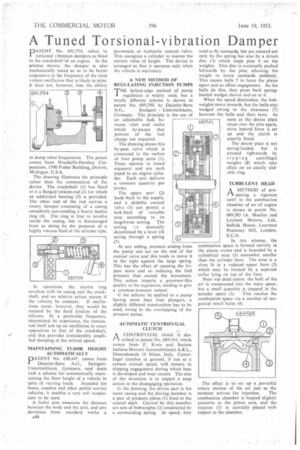
torsional vibration dampers as fitted to the crankshaft'of an engine. In the scheme shown, the damper is also mechanically tuned so as to be better responsive to the frequency of the most violent oscillation that is likely to arise. It does not, however, lose the ability to damp other frequencies. The paten comes from Houdaille-Hershey Cor poration, 1500 Fisher Building, Detroit Michigan, U.S.A.
The drawing illustrates the principle rather than the construction of the device. The crankshaft (1) has fitted to it a flanged torsion-rod (2) for which an additional bearing (3) is provided. The other end of the rod carries a rotary damper consisting of a casing completely surrounding a heavy inertia ring (4). The ring is free to revolve inside the easing, but is discouraged from so doing by the presence of a highly viscous thiid of the silicone type.
In operation, the inertia ring revolves with its casing and the crankshaft, and no relative action occurs if
the velocity be constant. If oscillations occur, however, they would be resisted by the fluid friction of the silicone. At a particular frequency, determined by experience, the torsionrod itself sets up an oscillation in exact opposition to that of the crankshaft, and this provides considerably amplified damping at the critical speed.
MAINTAINING FLOOR HEIGHT AUTOMATICALLY DATENT No. 690,447, comes from Daimler-Benz A.G., StuttgartUntertiirkheim, Germany, -and deals with a scheme for automatically maintaining the floor height of a vehicle in
spite of varying loads. Intended for buses, coaches and other public service vehicles, it enables a very soft suspension to be used.
A feeler arm measures the distance between the body and the axle, and any deviation from standard works a A40 pneumatic or hydraulic control valve. This energizes a cylinder to restore the correct value of height. The device is arranged so that it operates only when the vehicle is stationary.
A NEW METHOD OF REG U LATIN G INJECTION PUMPS
THE helical-edge method of pump regulation is widely used, but a totally different scheme is shown in patent No. 689,599, by Daimler-Benz
A.G., Stuttgart Untertiirkheim, Germany. The principle is the use of an adjustable leak be tween inlet and outlet which by-passes that portion of the fuel charge not required.
The drawing shows this by-pass valve Which is connected to the outlets of four pump units (I). These operate in timed sequence and are each piped to an engine cylinder. Each unit delivers a constant quantity per stroke.
The upper port (2) leads back to the supply, and a slidable conical valve (3) can permit a leak-back of variable area according to its lengthwise setting. The setting s manually determined by a lever (4) acting through a spring (5).
At any setting, pressure ar sing from the pump can act on the end of the conical valve and this tends to move it to the 'right against the large spring. This has the effect of opening the bypass more and so reducing the fuel pressure that caused the movement. This action imparts a governor-like quality to the regulation, tending to give a constant-pressure output.
If the scheme he applied to a pump having more than four plungers, a slightly different construction has to be used, owing to the overlapping of the pressure pulses.
(2019;0.;
AUTOMATIC CENTRIFUGAL CLUTCH
A CENTRIFUGAL clutch is des
cribed in patent No, 689,543, which comes from F. Kreis and Societa Italiana Brevetti Automobilistici A.R.L., Domodossola 19 Milan, Italy. Centrifugal clutches in general, if run at a certain critical speed, wil4 remain in slipping engagement during which heat is developed and wear occurs. The aim of the invention is to impart a snap action to the disengaging operation.
In the drawing, the driven part is the outer casing and the driving member is a pair of pressure plates (I) fixed to the central shaft. Carried by this member arc sets of bobweights (2) constricted by a surrounding spring. At speed, they tend to fly outwards, but are resisted not only by the spring but also by a detent disc (3) which traps pins 4 on the weights, This disc is eventually pushed leftwards by the pins, allowing •the weight to move outwards suddenly. 'This causes balls 5 to force the plates apart and so effect engagement. As the balls do this, they press back springloaded wedges shown end-on at 6.
When the speed diminishes, the bob weights move inwards, but the balls stay wedged owing to the clearance (7) between the balls and their bore. As
soon as the. detent plate snaps over the pins again, extra inward force is set up and the clutch is smartly freed.
The detent plate is not sprineloaded, but is pressed rightwards by sloping centrifugal weights (8) which take effect on an axially slidable ring.
TURBULENT HEAD
A METHOD of pro
moting a vigorous swirl in the combustion chamber of an oil engine is shown in patent No. '689,585 (A. Mueller and Leyland Motors, Ltd., Suffolk House, Laurence Pountney Hill, London, E.C.4).
In this scheme, the combustion space is formed entirely in the piston crown and is bounded by a cylindrical nose (I) somewhat smaller than the cylinder bore. The nose is a close fit In a reduced upper bore (2) which may be formed by a separate collar lying on top of the liner.
Near top dead centre, the bulk of the air is compressed into the main space, but a small quantity is trapped in the annular space (3). This reaches the combustion space via a number of tangential small holes (4).
The effect is to set up a powerful rotary motion of the air just as the moment arrives for injection. The combustion chamber is located slightly eccentric to the piston axis, and the injector (5) is centrally placed with respect to the chamber.