


An Explanation of the Joy Valve Gear.
Page 10
Page 11
If you've noticed an error in this article please click here to report it so we can fix it.
MOST DRIVERS and mechanics are familiar with the Stephenson link motion, as used on steam wagons, with its two eccentrics and rods for each valve, and the disadvantage of notching up the motion, with its increased lead as the motion approaches mid-gear. But the Joy valve gear, usually classified as a radial gear, is so designed that constant lead is assured, whatever the cut-off, whilst a better
B26
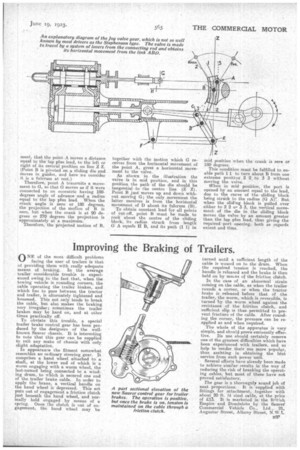
compression with quick opening and a quick cat-off is obtained. Apart ir0111 the satisfactory steam distribution obtained by the use of this valve gear, it is cheap to manufacture, and has few working parts -to cause engine friction. The principal features of the gear will be readily undsrstood from the illustration on the next page. The slide valve is made to travel by a system of levers from the connecting rod, ancl obtains its horizontal movement from the link. (A B D), shown dotted, the valve spindle being coupled to point A with a link (G A). Point D receives horizontal movement from link (CF), jointed to the connecting rod at C and to a rocking link it point ' E, which has its fulcrum at F. This rocking link is used to move point E as nearly as possible in a vertical line. The link (A B D) is so designed that point • D receives such horizontal move. ment, that the point.A moves a distance equal to the lap plus lead, to the left or right of its central position on line Z Z. (Point B is pivoted on a sliding die and moves in guides, and here we consider it is a fulcrum at rest.)
Therefore, point A transmits a movement to G, so that 0 moves as if it were connected to an eccentric having 180degrees angle of advance and a radius. equal to the lap plus lead. When the crank angle is zero or 180 degrees, the projection of the maim of B is zero, but when the crank is at 90 degrees or 270 degrees the projection is approximately at a maximum.
Therefore, the projected motion of B, together with the motion which G receives from the horizontal movement of the point A, gives a horizontal movement to the valve.
As shown in the illustration the valve is in mid position, and in this position the Path I)/ the die should be tangential to the centre line (Z Z). Point B just moves up and down without moving G; the only movement the latter receives is from the horiZontal movement of D about its fulcrum (13). To obtain constant lead for all points of "cut-off, point B must be made to rock about the centre of the sliding block, its radius struck from length G A equals II B, and its path (1 1) in mid position when the crank is zero or 180 degrees.
This condition must be fulfilled to enable path 1 1 to turn about B from one extreme position , 2 2 to 3 3 without moving the valve.
When in mid position, the port is opened by an amount equal to the lead, due to the curve of the sliding block being struck to the radius (0 A)! But when the sliding block is pulled over either to2 2 or 3 3, the vertical movement of the die in the sliding block moves the valve by an amount greater than the lap plus lead, thus giving the required port opening, both as regards extent and time.