


A Versatile Tractor
Page 60
If you've noticed an error in this article please click here to report it so we can fix it.
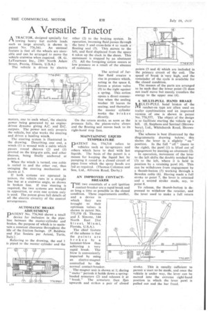
A TRACTOR, designed specially for I—% towing heavy but mobile loads such as large aircraft, is shown in patent No. 776,541. An unusual feature is that all the wheels are steerable and can be arranged to move the vehicle crabwise when required. (R. G. LeTourneau Inc., 2301 North Adam Street, Peoria, Illinois, U.S.A.)
The vehicle is driven by electric motors, one to each wheel, the electric power being generated by an enginedriven dynamo giving A.C. and D.C. outputs. The power not only propels the vehicle, but also works the steering and drives a hauling winch.
The steering system is illustrated in the drawing. Describing one end, a winch (I) is wound with a cable which passes round sheaves (2) and (3) pivoted on the king-pin axis, and other sheaves, being finally anchored at points 4.
When the winch is turned, one cable is reeled in and the other out, thus swinging the steering mechanism as shown at 5.
If both systems are operated in unison, the vehicle runs in a straight line but at a crabwise angle, as shown in broken line. If true steering is required, the two systems are worked in opposition, or even one system only is used. The patent gives full details of all the electric circuitry of the control arrangements.
AUTOMATIC BRAKE ADJUSTMENT
DATENT No. 776,960 shows a small device for inclusion in the pipeline between the master-cylinder and brakes, the purpose of which is to maintain a constant clearance throughout the life of the friction facings. (P. Baldwin and Fiat Societa per Azioni, Turin, Italy.) .
Referring to the drawing, the end 1 is piped to the master cylinder and the
other (2) to the braking system. In operation, incoming fluid passes through the bore 3 and cross-hole 4 to reach a floating seal (5). This moves to the left, and fluid displaced from the space 6 takes up the slack in the shoes. This movement is stopped by an abutment (7). All the foregoing action occurs at low pressure as a result of the absence of resistance,
The arrival of further fluid creates a rise in pressure which, acting in the space 8, forces a piston valve (9) to the right against a spring. This action opens a direct connection when the sealing washer 10 leaves its seating, and thereafter the master cylinder works the brakes directly.
On the return stroke, as soon as the pressure falls, the piston-valve closes and the floating seal moves back to its right-hand stop face.
MAINTAINING LIQUID TEMPERATURE
PATENT No. 774,718 refers to vehicles such as tar-sprayers and others which have to deal with hot liquids. The basis of the patent is a means for keeping the liquid hot by pumping it round in a closed circuit of pipes from which the spray heads are fed as required. (Thomas Coleman and Son, Ltd., Alfreton Road, Derby.) AN IMPROVED CONTACTBREAKER THE two essentials of a coil ignition contact-breaker are a rapid break and as long a time as possible in the closed condition. These requirements conflict, and a device in which they are brought to their optimum values is shown in patent No. 775,570 (S. Thomas and I. Simone, 194 North East 21st Street, Miami, Florida, U.S.A.).
The chief feature of the scheme is that the points are broken by a hammer-blow thus achieving a very rapid break. The blow is conveniently imparted by using an electro-magnet
controlled by the normal contact-breaker.
. The magnet unit is shown at I; during " make" periods it holds down a springloaded armature (2) and releases it at "break." The armature then flies upwards and strikes a pair of closed points (3 and 4) which are included in the primary circuit of the coil. The speed of break is very high, and the remainder of the cycle is available for the closed condition.
The masses of the parts are arranged to be such that the lower point (3) does not itself move but merely transfers the energy to the upper one (4).
A MULTI-PULL HAND BRAKE NAULTI-PULL hand brakes of the JY1 ratchet-on type are often used on trailer combinations and an improved version of one is shown in patent No. '776,557. The object of the design is to facilitate starting the vehicle up a hill. (E. Stephens and Sentinel (Shrewsbury), Ltd., Whitchurch Road, Shrewsbury.) The, scheme is best illustrated by the diagrammatic drawing below; this shows the lever in a slightly " on " position. In the full " off " (more to the right), the pawl (I) is lifted out of engagement by meeting an abutment (2).
In operation, movement of the lever to the left shifts the doubly notched bar (3) to the left, where it is held in position by a retaining pawl (4). This can be withdrawn frnm engagement by a thumb-button (5) working through a Bowden cable (6). Having made a full stroke to point 7, the lever is returned and a second stroke made, say, to point 8.
To release, the thumb-button is depressed to withdraw the retainer, and the lever used to make a full return
stroke. This is usually sufficient to permit a start to-be made, and once the vehicle is under way, the lever can be moved into the extreme right-hand position in which the lever pawl is pulled out and the bar freed.