


Casting Complex Crankshafts A Resume' of Patent Specifications that Have
Page 52
If you've noticed an error in this article please click here to report it so we can fix it.
Recently Been Published AN interesting method of crankshaft manufacture is described in patent No. 429,576 by the Ford Motor Co., Ltd., 88, Regent Street, London, W.1. The scheme is particularly applicable to crankshafts having 90 degree crankpin spacing, such as used in a V-type eight-cylindered engine. Owing to the complex nature of the required mould, the casting of such a shaft has, hitherto, been commercially impracticable.
The suggested mould is built up from a number of superimposed discs made of core sand, two being required
for each bearing. Metal plates are placed at the top and the bottom, the whole being clamped together by long bolts. A further interesting point is the intentionally distorted setting of th.) mould, proportioned so that, upon cooling, the crankshaft is substantially in line.
Provision is made for definitely locating each disc with respect to that • below it, and, doubtless, advantage is taken of the means provided for doing this in the process of forming the mould in each disc.
Combustion-chamber Progress.
PATENT No. 429,685 gives details of a combustion chamber of the " last-moment-kick " variety, in which the low piston velocity near top dead centre is counterbalanced by an aperture of decreasing size. The patentee is A. Vignery-, 7, Rue du Ponton, Gand, Belgium.
In the drawing, the chamber (1) has an aperture with a horizontal face (2) and a raised face (4). When the piston is low in the cylinder, both the faces are open, bult as the piston nears the top, face 2 becomes ineffective, owing to the obstruction caused by the recess (3) in the piston. The patent is principally based on-the fact of the opposing wall (5) of the chamber being substantially tangential to the general curve of the walls.
Running on Low-grade Fuel.
THE use of heavy tar oils in inter' nal-combustion engines seems to be attractive to inventors, in spite of the many difficulties encountered in respect of idle running and low loads. In patent No. 420,673, Daimler-Benz A.G., Stuttgart. Germany, deals with a scheme in which the engine pre-corn
bustion chambers are electrically maintained at a high temperature during slow running, the operation of the device being effected automatically.
The accompanying drawing shows
B42
the pre-combustion chamber surrounded by an electric incandescent ring (2). The accelerator pedal controls a switch (1) in such a manner that the chamber is heated at only low speeds. In order to provide the current necessary for long-period operation, it is proposed that a larger dynamo be fitted; even so the scheme is stated to
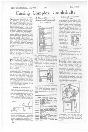
be superior to and simpler than those of the two-fuel type. The other two switches enable the circuit to be permanently broken, or closed independently of the accelerator pedal. Facilitating Interchangeability in Pumps.
ACCORDING to Robert Bosch AG:, Stuttgart, Germany, the extremely high standard of accuracy required in injection pumps renders interchangeability difficult, if not impossible. This concern discloses in patent No. 429,667 a packing washer intended to seal the joint between the cross bore (1) and the cylinder casing (3). This washer (2) is made of lead, shaped to fit the surrounding space and is compressed during assembly by a screwed ring. The conduit so arranged is stated to form part of an h y d raulically operated control of a compressed-air starting system.
It will be observed that there is a parallel extension on the screwed ring to prevent expansion of the lead inwards.
A New Valve-gear Design.
cROM J. D. Pearson, " Lynedene,"
Littleover, Derby, comes patent No. 429,689, showing a design of valve gear for which several advantages are claimed: The drawing shows the scheme clearly, and needs no explanation, except to state the combustion chamber is approximately pear-shaped having its smaller end around the exhaust valve (1).
Attention should be drawn, however, to the fact that the head is cut away around the exhaust valve, to allow free passage of the gas, and that the final stages of combustion are in the coolest part of the chamber.
The benefits claimed are better "
breathing" of the gas flow, a lessened tendency to detonate, and the protection of the gasket from high temperatures due to the shoulders 2 and 3..