


Patents Completed.
Page 24
If you've noticed an error in this article please click here to report it so we can fix it.
Complete specifications of the following patents will be sent to any address in the United Kingdom upon receipt of eightpence per copy at the Sale Branch, Patent Office, Holborn, W.C.
SIDE-CAR.—Fulfurd and Howe.—No. 26,623, dated 15th November, 1910.—The drawings attached to this specification show a form of construction for the
framework c I a side-car to carry a box M the form of a goods' receptacle, such as might be used by tradesmen. The object. of the invention is to provide a wellbalanced structure with a strong frame work. Two squares composed of tubular rails are joined at their corners by vertical members, the wheel spindle is attached to the middle of one side, and is continued as a dropped axle. An extension is formed on the near lower rail to be connected to the motorcycle near the head by the usual form of attachment, whilst the upper rail is connected by a diagonal stay, part of which is shown. This construction enables the centre of gravity of the receptacle for goods to be kept low, thus ensuring a good balance of the side-car.
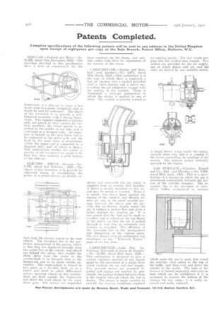
ELECTRIC DRIVE.—Stevens.—No. 2.700, dated 3rd February, 1910.—The object of this invention is to provide an improved means of transmitting the power in a petrol-electric or electric ve
hick from the electric motors to the road wheels. The invention lies in the particular arrangement of the motors, which is that they are displaced laterally from the centre line of the vehicle, and placed one behind the other; this enables the chain drive from the motor to the countershaft to be brought close to the framework and to be made readily accessible. The countershaft is formed in two parts as a divided shaft, or as a sleeve and shaft to allow differential action; sprocket wheels on this countershaft are fixed outside the framework and drive the mad wheels by the usual chain gear. The motors are suspended
from crossbars on the frame, and suitable radius rods allow for adjustment of the tension of the chain.
CARBURETTER—Napier and Sons, Ltd., and Another.—No. 6,671, dated 16th March, 1910.—This carburetter is of the type in which there is employed a fuel jet opening into a conduit provided with a valve seating and a sleeve surronnding the jet adapted to engage with the seating iii the conduit. There is illustrated it twin-jet carburetter in which the device is applied to one of them. The conduit is suitably formed as shown and surrounds the jet which is supplied from lilt annular fuel chamber. A sleeve is loosely mounted on this jet, and may be raised or lowered. When it is raised, this sleeve bears against the seating of the conduit, and thereby admits air only in the small annular passage between the sleeve and the jet; with this air flowing closely round the jet, it induces a greater flow and gives a tidier mixture for starting up. It is also stated that the fuel can be made to overflow and to collect on the top flange of the sleeve, so that the air is snaked through it, and thus an extremely rich mixture is provided. The efficiency of the invention lies in the arrangement and dimensions of the various parts. The new Napier twin-jet carburetter was mentioned 41IL the " Motoreab Topics " page of our last issue.
CARBURETTER.—Lake (Soc. An. Fahrique Natiortale d'Armes de Guerrel. —No. 15,524, dated 25th June, 1910.— This carburetter is designed to give a correct explosive mixture at any engine speed by the movement of a single lever which controls the air and fuel supply. Two grooved sectors are mounted together and engage one another by gear wheels. the passage formed between them is the conduit through which the fuel is drawn. The groove is made variable to provide the vaeying conditions required
for varying speeds. The fuel nozzle projects into the conduit thus formed. Two orifices are provided for the air supply, one of which draws cold air, and the other air heated by any suitable means.
A single sleeve, lying inside the casing, controls these two, and it is coupled to the levers controlling the position of the sectors. The mixture passes vertically upwards to the engine.
GAS FURNACE.—Fletcher, Russell and Co., Ltd., and Fletcher.—No. 9,940, dated 23rd April, 1910.—This is a speetfication of a furnace in which the gas is introduced tangentially towards the bottom of the crucible chamber. The invention lies in the provision of cylindrical hales constructed in sections
which cause the gas to pass, first round the crucible, then rising to the top of the baffle, and then over and down the outside to the outlet. The base of the furnace is formed separately and rests or, bars which can be withdrawn if it is necessary to remove the bottom of the furnace for any cause; it is easily removed and easily replaced.