 1
1 2
2 3
3 4
4 5
5 6
6 7
7 8
8 9
9 10
10 11
11 12
12 13
13 14
14 15
15 16
16 17
17 18
18 19
19 20
20 21
21 22
22 23
23 24
24 25
25 26
26 27
27 28
28 29
29 30
30 31
31 32
32 33
33 34
34 35
35 36
36 37
37 38
38 39
39 40
40 41
41 42
42 43
43 44
44 45
45 46
46 47
47 48
48 49
49 50
50 51
51 52
52 53
53 54
54 55
55 56
56 57
57 58
58 59
59 60
60 61
61 62
62 63
63 64
64 65
65 66
66 67
67 68
68 69
69 70
70 71
71 72
72 73
73 74
74 75
75 76
76 77
77 78
78 79
79 80
80 81
81 82
82 83
83 84
84 85
85 86
86 87
87 88
88 89
89 90
90 91
91 92
92 93
93 94
94 95
95 96
96 97
97 98
98 99
99 100
100 101
101 102
102 103
103 104
104 105
105 106
106 107
107 108
108 109
109 110
110 111
111 112
112 113
113 114
114 115
115 116
116 117
117 118
118 119
119 120
120 121
121 122
122 123
123 124
124 125
125 126
126 127
127 128
128 129
129 130
130 131
131 132
132 133
133 134
134 135
135 136
136 137
137 138
138 139
139 140
140 141
141 142
142 143
143 144
144 145
145 146
146 147
147 148
148 149
149 150
150 151
151 152
152 153
153 154
154 155
155 156
156 157
157 158
158 159
159 160
160 161
161 162
162 163
163 164
164 165
165 166
166 167
167 168
168 169
169 170
170 171
171 172
172 173
173 174
174 175
175 176
176 177
177 178
178 179
179 180
180 181
181 182
182 183
183 184
184 185
185 186
186 187
187 188
188 189
189 190
190 191
191 192
192 193
193 194
194 195
195 196
196 197
197 198
198 199
199 200
200 201
201 202
202 203
203 204
204 205
205 206
206 207
207 208
208 209
209 210
210 211
211 212
212 213
213 214
214 215
215 216
216 217
217 218
218 219
219 220
220 FREE WHEEL POSSIBILITIES
Page 113
Page 114
If you've noticed an error in this article please click here to report it so we can fix it.
for Buses and Coaches.
DURING the past few months great interest has been shown in free-wheel devices for use on private cars and, in addition, it is an open secret that a number of important coach and bus operators has been experimenting with this new mechanism. Consequently, it is opportune in this special number of The Commercial Motor to review a transmission development which, whilst atpresent in its infancy, may soon exercise a widespread= influence upon chassis design.
The action of the free wheel is easy to understand, as it ig entirely• analogous in its effects to the mechanism fitted to the ordinary bicycle. Just as the rider can at any time cease pedalling and allow the driving wheel to overrun, so, in the case of a motor vehicle, closing the throttle permits the engine to drop .down to idling speed, while the vehicle coasts freely forwards. The free wheel employed resetukles a ratchet in action, but conveys the drive by friction instead of through pawls and teeth and it may be fitted either behind the gearbox DT in the back axle.
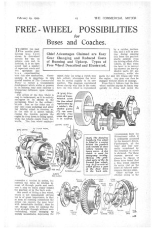
One result of fitting a free wheel, which is not immediately obvious but is of great importance, is that so soon as coasting commences the driver can operate the gear lever with remarkable facility; thus., he can change down by pushing the lever straight through without even declutching, whilst changing up merely necessitates depressing the clutch fully (to bring a clutch stop into action), whereupon the lever can be moved rapidly to its new position. The diagram reproduced shows clearly why this is the case; here the free wheel is represented
by a ratchet mechanism, and it will be seen that during coasting this frees the gearbox shafts entirely from the driving effect of the vehicle, so that when the lever is in neutral (as shown) the heavily shaded parts (0) are stationary, whilst the parts (A) and (B) rotate idly with the engine. .Any gear can then be engaged without shock or damage, From this it follows that the free wheel enables anyone to learn very quickly tO drive mid saves the transmission from the ill-treatment which it is ordinarily accorded by the inexpert driver. Furthermore, all the wear and tear normally occasioned by the reversals of stress is obviated. For these reasons several engineers in charge of fleets have' fonnd that a free wheel justifies its extra cost on the ,scored' reduced maintenance charges alone.
Other savings are effected owing to the
considerable portions of a journey which the free-wheel vehicle covers by coasting. The exact saving depends upon speed and road conditions but averages 15 per cent. on petrol and an almost equal amount on oil. Other factors are reduced tyre bills and the less frequent occasions on which the vehicle is laid up for -decarbonizing or overhaul.
Turning to the Oisadvantages, the first and most obvious is that much more work and reSponsibility are thrown upon the brakes when a free wheel is fitted. In fact the braking system mast then be beyond reproach and, for all practical purposes, incapable of failure. It is true that all the free wheels so far produced can fairly easily be locked to regain the use of the engine as a brake, but this procedure needs presence. of mind and occupies perhaps a couple of seconds; neither the alertness nor the time may be available in • the case of a sudden brake failure.
Arising out of this is the question whether a free wheel vehicle is sufficiently safe on a greasy road; this would seem to depend upon the general design of the vehicle, the smoothness of the brakes and the way in which the free wheel is applied.
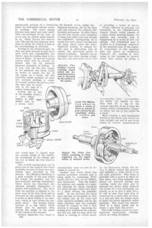
Only a brief consideration can be given here to the types of free wheel available, as most of these have previously been described iiu this journal. The Humfrey-Sandberg a good example of the type which tits behind the gearbox, and the part-sectioned drawing reproduced, which shows the free-wheel mechanism partially . dismantled, is almost self-explanatory. The drive from the gearbox is applied to the outer race of the free wheel and is ccnveyed by the gripping action of a series of skew rollers to an inner race, which in turn drives the pro
peller .shaft. The locking device consists of a dog clutch which should only be operated after revving the engine to the speed of the vehicle at the Moment.
Another important free wheel is D24
the De Lavand, which, unlike the Humfrey-Sandberg, MS in the back axle and replaces the ordinary differential mechanism. In effect there are two free wheels, each consisting of cams and rollers and each driving one half-shaft; consequently, on a corner the outer wheel overruns and the inner wheel takes the drive. Improved stability is claimed for this type of differential, and, of course, the free-wheel action is always available. Matters are so arranged that after moving a locking lever the free-wheel act bri will automatically cease so soon as the. engine is revved up.
Another free wheel which has become prominent .recently and is being made by Armstrong, Whitworth and Co., Ltd., is the Milian',
also illustrated. This fits behind the gearbox and consists of a member carrying six claws conveying the drive through rollers and shoes to a drum driving the propeller shaft. In one direction the shoes have freedom of movement so that the rollers ride up the cams and exert outward pressure, but in the other direction tbey are normally located by tongues so that a free overrun is obtained. r Operating the locking lever withdraws the tongues, but this can only be done when the engine is running at vehicle speed; SO providing a factor of salary.
Wholly. different in principle and conception is the Clayton-Currin Coaster Clutch, which consists of a ;plate clutch mounted behind abe gearbox and • normally held in engagement by a series of stiff coil springs. The withdrawal gear is coupled to a diaphragm connected to the induction pipe of the engine. In consequence of this ingenious plan the clutch is withdrawal whenever the throttle is shut, owing to the increase in vacuum which then occurs,so giving a Tree-wheeling effect. t urthermore, the driver can readily at any time turn off a tap in the vacuum pipe-line so a.s to keep the coaster clutch permanently engaged to obtain the use of the engine as a brake.
More recently a new mechanism known as the Pitter free wheel has been brought out and is now being tested by various manufacturers.
As the illustration shows, this device is placed behind the gearbox and embodies a drum driven from the main gearsh aft. This drum is provided with a groove in which fit four shoes, two being normally employed for forward driving and coasting, while the other pair is released • for action when .required (by means of a cam mechanism not shown) so as to give a solid drive. It will be seen that each shoe is connected by a short link, or strut,. to a hub and that the torque tends to make the struts approach radial positions. The shoes are thereby tilted to a slight extent and so obtain a grip upon the groove.
This brief rasumd covers the more important mechanisms, although others are being developed.