


Patents Completed.
Page 22
If you've noticed an error in this article please click here to report it so we can fix it.
Improving Compressed-air Starting. An Oscillating Rotary-Valve Engine.
HE WOLSELEY TOOL AND MOTOR CAR CO., LTD., and A. J. ROWLEDGE, No 1953, dated 24th January, 1913.—When a special valve is used for admitting compressed air to the working cylinders of a motor for starting, it has hitherto been expeed to the direct heat of combustion and is apt. to de
teriorate rapidly. Also the very high explosion pressure tends to increase the leakage back through the valve. According to this invention the inlet valve for compressed air is situated at one side of the cylinder and communicates with it by a small paesage, the end of which is covered by the piston when at the top of its stroke. By making the passage sufficiently small, there is only slight circulation of the products of combustion in the valve pocket; it thus remains filled with exhaust gases, and since it is not opened to the combustion chamber until the piston has moved a short distance outward, the temperature of the gases which enter it is reduced considerably below what it was at the moment of ignition.
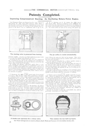
V. REINHARD, No. 8604, of 1913, dated under International Convention, 26th October, 1012.—This specification describes an oscillating rotary valve, which consists ef a cylinder with a longitudinal slot in one side. This slot is reciprocated across the inlet and exhaust ports, and communication is established with the cylinder through the open end of the valve. The valve is mounted on a stem which carries an arm at its lower end; the arm is provided with two rollers engaging cams shaped to give the desired motion.
A double cam is used as shown in the drawing ; the halves of the cam are of different diameters, so that each roller bears continuously on one haif. As these rollers invariably rotate in the same direction, and are always held in contact with the cam, no noise is produced ne reversal of motion of the valve.
It. %V. A. BREWER and C. H. JONES., No. 6323, dated 14th March, 1913. Patent of Addition to No. 20495112.—In this carburetter the float chamber is situated at the bottom of the casing, and the petrol passes from it to a centrally situated jet. Air enters from one side of-the casing, and passes up
ward, lifting the main air valve in its passage. This valve rests on a tapered seating and has a hollow stem within which the fuel jet is situated. The jet itself is controlled by a slotted spindle which is moved up and down in it to vary the opening.
This spindle is carried by a lever pivoted upon the body of the main air valve, and the other end of the lever engages a stop on the easing of the carburetter. The movement of the air valve thus alters the opeuipg of the jet according to the conditions of running.
The stop on the casing is, according to this invention, made, adjustable so that the setting of the lever carrying the slotted spindle can be varied while the carburetter is working.
WrrzEr. and A. FEDERER, No. 18,007, dated 7th August, 1913. Patent of Addition to No. 3904/13.—The original tire, of which this specification describes an improvement, had a core of alternate layers of air, rubber and fabric.
According to the wesent invention the outer cover is made integral with tile-core by vulcanizing all the parts together. This obviates a difficulty which has, hitherto, been experienced through the heat, generated by friction between the cover and the core, causing the rubber to perish. This tire also gives greater elasticity, since the air chambers are closed in all directions, although any collapse is prevented by the layers of fabric. The tire is secured in place by a detachable rim, and is preferably vulcanized on a steel band.