


SETTING THE LIMIT
Page 85
Page 86
If you've noticed an error in this article please click here to report it so we can fix it.
Top speed limiters will be mandatory on all new trucks over 7.5 tonnes registered after 1 August 1992. But it is not only new trucks that will be affected. By 1 August 1993 trucks over 16 tonnes that were registered after 1 August 1988 will have to be retrofitted with limiters. The details have yet to be finalised, but it is clear that many thousands of trucks will be affected.
The cost of a limiter is not insignificant, and many operators will want to minimise the outlay by having their workshops fit the limiters.
Workshop visited Lucas Kienzle's training centre to see how it's done. Operator's and independent workshops' staff can attend the courses which cost around /200. Product service engineer John Skidmore handled the job: he explained that two principles must be appreciated if a limiter is to be fitted economically and safely. First the limiter interferes with the accelerator linkage, so correct fitting is essential for safety reasons. Secondly, for the reasons explained below, the most economical way to connect the limiter's electrics in compliance with the regulations is to take it to a combined tachograph/limiter centre.
We watched a limiter being fitted to a Leyland Daf 80 Series 4 x 2 tractive unit with a 224kW (300hp) 11.6-litre Daf engine. When fitting a limiter the vehicle make, model, engine spec, pump type, linkage configuration and any extras fitted all have to be considered.
Lucas Kienzle assembles all relevant components into more than 70 basic kits, but complications can arise when extras like oil coolers and cab heaters are fitted. Probably the easiest way to get the right parts is to take the vehicle to the local speed limiter fitment centre and ask them to specify the relevant kit.
The limiter will need to pick up a speed signal, probably from the tachograph. That will entail breaking the seals on the back of the tacho. If the seals are broken at the tachograph centre it can reseal the unit without re-calibrating if the seals are broken when the vehicle comes in, the unit will have to here-calibrated.
Many speed limiter centres are also tacho centres so it could be worth arranging for the limiter to be connected and calibrated when ordering the kit.
The Lucas Kienzle kit contains a schematic drawing, the electronic control module, the limiter actuator and cradle, the secondary lever, and a length of studding. Installing a limiter should take between two and four hours, depending on the vehicle and the fitter's experience.
To start the process tilt the cab and refer to the drawing to find out where to attach the actuator cradle to the vehicle.
When fitting the two pivot pins don't forget the spring washers beneath the bolt heads. Fit the actuator onto the pivot and tighten the pins to lock them: if the washers are left out, the pins will push into the actuator and damage it.
The cradle bracket can now be fitted to the vehicle in the position shown on the drawing.
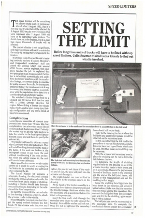
At the heart of the limiter assembly is a secondary lever between the pump arm and the throttle linkage. Skidmore advises that the secondary arm is assembled before it is fitted to the pump arm.
Insert the link stud's shaft through the secondary arm (from the side without the bearing), then add the washer and lock nut. Once the nut is tightened the secondary Refer to the drawing to check where the ball joint and accelerator linkage should be attached on the secondary lever.
In this case attaching the link stud to the pump lever is easy as Bosch pump accelerator arms have two tapped holes which can be used. On other makes some drilling may be necessary.
With the actuator and secondary lever in place the studding can be cut to form the link between the two.
To determine the length of studding required refer to the drawing to see if the actuator trunnion needs to be in or out and set it accordingly. Measure the gap between the end of the brass insert in the trunnion and the end of the ball joint sleeve; add 20mm to this measurement and cut the studding to that length.
Screw the studding hand tight into the brass insert in the trunnion and secure it with a locicnut Make sure that the trunnion does not rotate during this operation. Disconnect the ball joint from the secondary arm and fit it to the studding, again securing it with a locknut
The ball joint can now be reconnected to the secondary arm. To complete the mechanical fitment attach the accelerator linkage to the secondary arm in the position indicated on the drawing. It is important to check that full accelerator movement is still available (this needs two people).
Electrical connections start with the cable attached to the actuator. This cable is only about 500mm long and ends with a plug enabling the longer cable, which comes in the kit, to be connected.
The second cable is routed along the chassis and into the cab. Use ties to secure the new cable to existing pipes or cables to avoid routing problems.
The control module has to be sited inside the cab as it is not weather proof. Fitters in fleet workshops may wish to locate the control module in an areas where drivers will not be tempted to tamper with it — close to the fuse box is a good choice.
Having secured the control module by means of self tapping screws the electrical connections can be made.
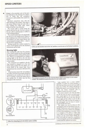
After routeing the cable from the actuator to the control module put the end through the sealing cap before cutting off the excess wire. There is no requirement for a limiter warning light in the UK so the red wire from the actuator should not be connected to the module.
The connectors are supplied in the kit. They should be crimped on to the wire before being pushed into the plastic connector block in the correct hole. Once pushed home the connector will lock in the block.
If the trunnion rests in the 'out' position, the yellow wire from the actuator should be connected to pin number six. If it rests in the 'in' position, connect the yellow wire to pin number five. In either case the blue wire goes to the vacant pin. Later modules have a cruise control capability. To make use of this function, a wire from pin three must be led to an earth point via a switch. The vehicle will then be held at the speed it was travelling when the switch was closed. A separate wire is needed to connect pin seven to earth.
The excess actuator wire that has been cut off can now be used to provide power and a speed signal to the control module. Connect the blue wire to pin nine, the red to pin eight and the yellow to pin 15. The free end of the cable can then be routed to the tachograph area but leave ii unconnected and all seals intact.
The vehicle can now be driven to the tachograph centre for the limiter to be connected. Until power and a speed signal are supplied to the unit it will not do anything, so even if the installation is incorrect there is no danger to the driver or other road users. Most of Lucas Kienzle's tachograph centres are also speed limiter fitting centres, so its staff can make the connections to the tachograph, ensure the installation is correct and also calibrate the limiter.