


An Electrically Operated Gearbox
Page 58
If you've noticed an error in this article please click here to report it so we can fix it.
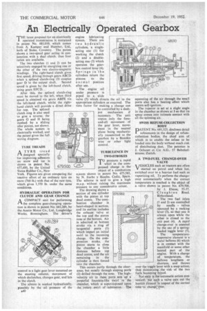
THE latest proposal for an electrically operated transmission is contained in patent No. 681,010, which comes from A. Kamper and Humber, Ltd., both of Stoke, Coventry. The patent shows a two-speed gear acting in conjunction with a dual clutch, thus four ratios are available.
The two clutches (I and 2) can be selectively engaged by energizing one or the other of the two cleetro-magnetic windings. The right-hand clutch gives first speed, driving through gears ABU) when a splined clutch-ring (3) couples gear 0 to the output shaft. Second speed is given by the left-hand clutch, using gears EFCD. .
After this, the splined clutch-ring must be moved to the left, when third speed is obtained via gears ABFE via the left-hand clutch, whilst the righthand clutch will provide a direct drive for top. The splined clutch ring is also used to give a reverse, the gears G and H being meshed by a sliding idler pinion, not shown. The whole system is electrically worked, and the patent gives the full wiring diagram.
-TYRE TREADS
A TYRE tread
designed specially for improving adhesion on snow and ice is shown in patent No. 677,400, by the United States Rubber Co., New York. Figures are given comparing the tractive effort of an ordinary tyre on snow (760 lb.) with that of the new tyre, which gives 1,370 lb. under the same conditions.
HYDRAULIC OPERATION FOR
CLUTCH AND GEAR CHANGE A COMPACT unit for performing I-1 the complete gear-changing opera-tion is shown in patent No. 681,2139, by the Austin Motor Co., Ltd., Longbridge Works, Birmingham. The , driver's
engine lubricating system. There are two hydraulic cylinders, a singleacting one (1) for working the clutch (2) and a doubleacting one (3) which operates the gearbox control lever (4). Springs in the cylinders return the pistons to the normal position after use.
The engine oil under pressure is piped to a slide valve (5) which directs the oil to the appropriate cylinders as required. The time factor for making a change can be controlled by a dashpot mechanism if necessary. The unit copies only the foreand-aft movement of the gear lever, movement in the neutral plane being mechanically transmitted to the gearbox by a Bowden wire or other light control.
TURBULENCE IN TWO-STROKES
TO promote a rapid whirl in the compressed charge is the object of a combustion system shown in patent No. 675,582, by N. Iturbe y Basabe, Cadiz, Spain. The scheme is said to give a high m.e.p. without raising the maximum pressure to any considerable extent.
The drawing shows a section of one cylinder with the piston at top dead centre. The combustion chamber is heart-shaped in section, and its outline includes the exhaust valve at the top and the piston nose at the bottom. Air is admitted at bottom stroke via a ring of tangential ports (1) which impart an initial swirl to the incoming charge. On the compression stroke, the piston starts to close the chamber a little distance before top dead centre, and the air remaining in the cylinder is then forced into the chamber.
This occurs partly through the clearance, but mostly through sloping ports (2) drilled through the nose. The highvelocity air in these ports .sets up a powerful fountain-like swirl in the chamber, which is superimposed upon the. rotary, swirl of admission. The squeezing of the air through the small ports also has a heating effect which assists self-ignition.
The injector is set at a slight angle in the chamber as shown at 3 so that its spray comes into intimate contact with all the spinning air.
SWISS REFUSE-COLLECTION BODY
DATENT No. 681,323, discloses detail
refinements in the design of refusecollection bodies, the chief aim of which is to enable the refuse to be loaded into the body without much risk of distributing dust. The patentee is J. Ochsner et Cie A.G., 57 Bahnhofstrasse, Zurich.
A TWO-FUEL CHANGE-OVER VALVE
VEHICLES such as tractors are often V started on petrol and when hot, switched over to a heavier fuel such as vaporizing oil. To perform the changeover automatically when the correct temperature is reached is the object of a valve shown in patent No. 679,500. by J, Elston, 55-57, Claughton Road, Birkenhead.
The two fuel inlets (1 and 2) are controlled by needle valves operated by a rocking lever (3), so that one is always open while the other is closed to the exit port (4). A rapid change-over is ensured by the use of a springloaded toggle lever (5).
The temperatureresponsive element is a metal bellows (6) which is in contact with the manifold or some other heated part of the engine. With a change of temperature, the bellows lengthens or shortens, and throws over the toggle lever with a snap action, thus minimizing the risk of the two fuels becoming mixed.
Not only is the automatic action convenient, but such a valve cuts out the human elemeut in respect of the correct tithe Ito change over.