


AN AUTOMATIC CHANGE-SPEED GEAR.
Page 28
If you've noticed an error in this article please click here to report it so we can fix it.
A Resume of Recently Published Patents.
THE OPERATION of a awash-plate, which, by its angularity with the main driving shaft, determines the gear ratio of the transmission, controls the change-speed gear which is described in epecification No. 184,447, by D. S. de Laxand. An interesting feature is that provision is made for automatic control of this device in such a manner that the gear ratio is varied in accordance with the load, thus, says the inventor, relieving the driver of the trouble of gearchanging, besides sav ing the engine and the other parts of the transmission, intervening betweee engine and gear,, from overload and misuse. Indeed, the principal -feature of the eeeseet invention, which is claimed to be an improvement
• on a former construction, described in patent specification No. 183,456 by the.same inventor, is the provision of ...means for varying automatically the relative angularity of the driving shaft and the swash member in accordance with the load.
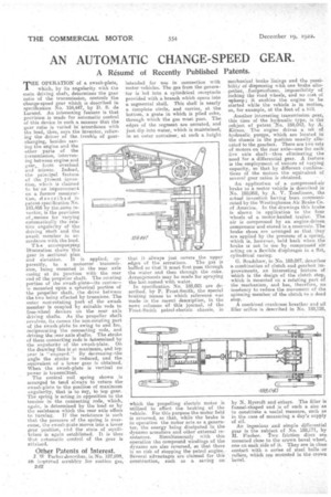
The accoMpanying
illustration showsthis
gear in sectional plan and elevation. It is applied, apparently, to a motorcar tralismission, being mounted in the rear axle easing at its junction with the rear end of the propeller shaft. The rotating portion of the swash-plate—its centre— is mounted upon a spherical portion of the propeller shaft, the drive between the two being effected by trunnions. The outer non-rotating part of the swash member is coupled by suitable rods to free-wheel devices on the rear axle driving shafts. As the propeller shaft revolves, its causes the non-rotating part of the awash-plate ,to swing to and fro, reciprocating the connecting reds, and driving the near axle shafts. The stroke of these connecting rods is determined by the angularity of the awash-plate. On the drawing this is at maximum, and top gear is " engaged." By decreasing the angle the stroke is reduced, and the equivalent of a lower gear is obtained. When the awash-plate is vertical no power is transmitted.
The conical coil spring shown is arranged to tend always to return the awash-plate to the position of maximum angularity, that is to say, to top gear. The spring is acting .in opposition to the tension in the connecting rods, which, again, is determined by the load or by the resistance which the rear axle offers to turning. If the resistance is such that the pressure of the spring is overcome, the swash-plate moves into a lower gear position, cud the state of equilibrium is again established. It is thus that automatic control of the gear is attained.
asseseemwdeme
Other Patents of !nterest.
Parkendescribes, in•No. 187,099, an inspeused scrubber for suction gas, 2.4.2 intended for use 111 connection with motor vehicles. The gas from the generator is led into a cylindrical receptacle provided with a branch which opens into a segmental shell. This shell is nearly a Complete circle, and carries, at the bottom, a grate in which is piled coke, through which the gas must pass. The edges of the segment are serrated, and just dip into water, which is maintained, in an outer container, at such a height that it always just covers the upper edges of the serrations. The gas is baffled so that it must first pass through the -water and then through the coke. Arrangements may be made for spraying the last-named with water.
In specification No. 188,021 are described, by P. Frost-Smith, the special braking means to which reference was made in the repent description, in the news columns of this journal, of the Trost-Smith petrol-electric chassis, in which the propelling electric motor is utilized to effect the braking of the vehicle. For this purpose the motor field is reversed, so that, while the brake is in operation the meter acts as a generator, the energy being dissipated in the dynamo armature and other external resistances. Simultaneously with this operation the compound windings of the dynamo are also reversed, so that there is no risk of stopping the petrol engine. Several advantages are claimed for this construction, such as a saving on mechanical brake linings and the possibility of dispensing with one brake altogether, leolproofness, impossibility of locking the road wheels, and no cost of upkeep; it enables the engine to be started while the vehicle is in motion, as, for example, at the foot of a hill.
Another interesting transmission gear, this time of the hydraulic type, is the subject of patent No. 188,043, by A. Kitson. The engine drives a set of hydraulic punips, which are located in the chassis in the position usually allocated to the gearbox. There are two sets of motors on the rear axle—one for each live axle shaft—thus eliminating the need for a differential gear. A feature is the employment of motors of varying capacity, so that by different combinations of the motors the equivalent of several gear ratios is obtained.
An application of a compressed-air brake to a. motor vehicle is described in No. 188,052, by A. V. Tomlinson, the actual invention having been communicated by the Westinghouse Air Brake Co. • of America. In the drawings this brake is shown in application to the four wheels of a motor-hauled trailer, The air is compressed by an engine-driven compressor and stored in a reservoir. The brake shoes are arranged so that they are applied by the pressure of a spring, which is, however, held back when the brake is not in use by compressed air acting on a flexible diaphragm in a flat, cylindrical casing.
G. Bradshaw, in No. 188,087, describes a combination of clutch and gearbox improvements, an interesting -feature of which is the design of the clutch step, which is moanted on a rotating part of the mechanism, and bas, therefore, no tendency to reduce the movement of the spinning member, of the clutch to a dead stop.
A combined crankcase breather and oil filler orifice is described in No. 188,128, by N. Rycroft and others. The filler is funnel-shaped and is of such a size as to constitute a useful measure, such as in the case of measuring a day's supply of oil.
An ingenious and simple differential gees is the subject of No. 188,171, by M. Fischer. Two friction discs are mounted close to the crown bevel wheel, one on each side of it. They are in close contact with a series of steel balls or rollers, which are mounted in the crown bevel.