


GARNER TRACTOR IMPROVEMENTS.
Page 22
If you've noticed an error in this article please click here to report it so we can fix it.
A Résumé of Recently Published Patent Specifications.
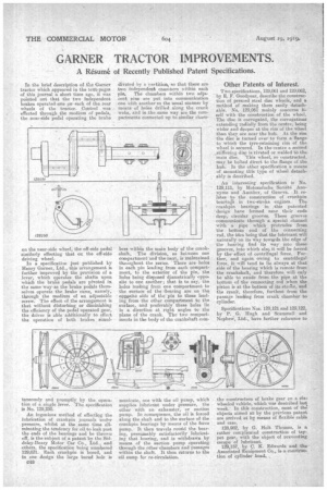
In the brief description of the Garner tractor which appeared in the texts pages of this journal a short time age, it was pointed out that the two independent brakes operated one on each of the rear wheels of the tractor. Control was effected through the medium of pedals, the near-side pedal operating the brake on the near-side wheel, the off-side pedal similarly effecting that on the off-side driving wheel.
In a specification just published by Henry Garner, Ltd., this arrangement is further improved by the provision of a lever, which operates the shafts upon which the brake pedals are pivoted in the same way-as the brake pedals themselves operate the brake cams, namely, through the medium of an adjustable screw. The effect of the arrangement is that without disturbing or diminishing the efficiency of the pedal operated gear, the driver is able additionally to effect the operation of both brakes siniul
taneously and promptly by the operation of a single lever. The specification is No. 129,230.
An ingenious method of effecting the lubrication of crankpin journals under .pressure, whilst at the ,same time eliminating the tendency for oil to leak past the ends of the bearings and be thrown off, is the subject of a patent by the Siddeley-Deasy Motor Car Co., Ltd., and others, the specification being numbered 129,031. Each crankpin is bored, and in one design the large bored hole is C48
divided by a raitition1,s0 that there are two independent chambers within each pin. The chambers within two adjaeent pins are put into communication one with another in the usual manner by means of holes drilled along the crank webs, and in .the.sarne way are the compartments connected up. to similar cham•
bers within the main body of the crankshaft, The division, as between one compartment and the next, is maintained throughout the series. There are holes in each pin leading from each compartment, to the exterior of the pin, the holes being disposed diametrically uppo. site to one another ; that is to say, the holes leading from one -compartment to the surface of the 'hearing are on the opnpsite side of the pin to those leading from the other compartment to the surface, and preferably these boles lie in a direction at right angles to the plane of the crank. The two compartments in the body of the crankshaft corn
muuicate, one with the oil pump, which supplies lubricant under pressure, the other with an exhauster, or suction pump. In consequence, the oil is forced along the shaft and to the surface of the crankpin bearings by means of the for pump. It then travels round the bearing, presumably satisfactorily lubricating that bearing, and is withdrawn by means of the suction pump operating through the other-chambers and passages within the abaft. It then returns to the oil sump for re-circulation.
Other Patents of Interest.
Two specifications, 129,061 and 129062, by E. F. Goodyear, describe the construction of pressed steel disc wheels,and a method of making them n easily detachable. No. 129,061 mainly concerns itself with the construction of the wheel. The disc is corrugated, the corrugations" extending radially from the centre, being wider and deeper at the rim of the wheel than they are near the hub. At the rim the disc is turned over to form a flange to which the tyre-retaining rim of the wheel is secured. In the centre a second _stiffening dise is riveted or welded to the. maindisc. This wheel, so constructed, may be bolted direct to the flange of the hub. In the other specification a means of mounting this type of wheel detachably is described.
An interesting specification is No. 129,111, by Motosacoehe Societe' Antinyme and Another, of Geneva. It. relates to the construction of crankpin bearinia in two-stroke engines. The crankpin bearings in this patented design have formed near their ends deep, circular grooves. These grooves communicate through a special channel with a. • pipe which protrudes from the bottom end of the connecting rod, the idea being that the lubricant will naturally on its Way towards the edge of the bearing find its way into these grooves, into which alsq it will be forced by the effect of centrifugal force. Further, and again owing to centrifugal force, it will tend to lie always at that side of the bearing which is remote from the crankshaft, and 'therefore will only be able to exude from the pipe at the bottom of the connecting red when the piston is at the bottom of its strolie, and the crank, therefore, furthest from the passage leading from crank chamber to cylinder.
Specifications Nos. 129,121 and 129,122, by P. G. Hugh and Scammell and NepheW, Ltd., have further reference to
the construction of brake ''veer en a six. wheeled vehicle, which was described last week. In this construction, most of the objects aimed at by the previous patent are arrived at by means of flexible cable and ease.
128,!2, by G. Holt Thomas, is a rather complicated construction of tappet gear, with the object of preventing escape of lubricant. 129,157, by C. K. Edwards and the Associated Equipment Co., is-a construction of cylinder head, ,