Independent Springing for „ Heavies A FORM of separate suspension stated to
Page 52

If you've noticed an error in this article please click here to report it so we can fix it.
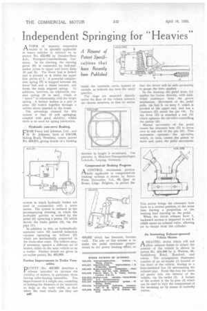
be specially applicable to heavy vehicles is referred to in patent No. 425,092 by Daimler-Benz A.G., Stuttgart-Untertiirkheim, Germany. In the drawing, the steering pivot (6) is connected by ball-andsocket joints to upper and lower links (8 and 5). The lower link is forked and is pivoted at 4, Whilst the upper link pivots at 1. A powerful compression spring (7) is trapped between the lower link and a frame bracket, and forms the main support spring. In addition, however, an adjustable tension spring (3.1 is used, which is
tuned" in relationship with the larger spring. A further feature is a pair of arms (2) bolted together through a rubber sleeve inserted in the frame. • The advantage claimed for this system is that of soft .springing, coupled with good stability, whilst there is no need for spring lubrication.
Hydraulic cum-servo Braking.
rROM Feeny and Johnson, Ltd., and M. E. Johnson, both of 134436, Ealing Road, Wembley, comes patent No. 424,911, giving details of a braking
system in which hydraulic brakes are used in conjunction with a servo motor. The system is outlined in the accompanying drawing, in which the hydraulic portion is worked by the pedal (2) operating a piston (3) which moves the brake piston (4), via the pipe (1).
In addition to this, an hydraulically operated valve (6) controls induction vacuum operating on bellows (5) which are mechanically connected to the brake-shoe cams. The bellows may, if necessary, operate a different set of brakes, either on the same vehicle or on a trailer. Further details are given in an earlier patent, No. 403,668.
Further Improvements in Trailer Turn tables.
ATENT No. 425,098 describes a I scheme intended to increase the stability of trailers, in particular those having roller-bearing turntables. The improvement is a simple one, consisting of Making the diameter of the turntable as lax-7e as the body width, so that when the road wheels rise they are
u42 inside the turntable circle, instead of outside as hitherto has been the usual practice.
The rings are mounted directly under the floor of the vehicle between the chassis members, so that no undue
increase in height is occasioned. The patentee is Bleichert-Transportanlagen G.m.b.H., Leipzig. Germany.
Compressed-air Braking Progress.
ACONTROL mechanism particularly applicable to compressed-air braking systems is shown by ServoFrein Dewandre, S.A., 68, Quai de Rome, Liege, Belgium, in patent No.
424,952 which has however, become void. The aim of this scheme is to make the pedal resistance proportional to the power braking effort, so that the driver will be able .accurately to gauge the force applied.
In the drawing ,the pedal lever, (1) applies the brakes directly, with additional assistance from the power mechanism. Movement of the, pedal_ pulls, via link 6, on lever 7, which is pivoted at the upper end, and has a clearance (5) about the pin (4). . To the lever .(7) • is attached a rod (3) which operates the air-valve controlling the piston (2).
Manual ,movement of the pedal causes the clearance bore (5) to move over to one side of the pin (4). This movement operates the air-valve, which, in turn, causes the piston to move and assist the pedal movement.
This action brings the clearance bore back to a central position, at the same time leaving a proportion of the braking load reacting on the pedal.
When the driver releases lever 1, backward motion is imparted to rod 3, which opens an exhaust valve, allowing air to escape from the cylinder.
An Interesting Exhaust-operated Vehicle Heater.
AHEATING device which will not allow exhaust fumes to vitiate the interior of the vehicle is shown in patent No. 424,368 by A_ Watson, 63, Southdown Road, Rornford, and others. The arrangement illustrated consists of an air-intake (1) located at the front of the vehicle, leading to a heat-insulated box (4) surrounding the exhaust pipe. From this box the warm air passes into the interior of the vehicle, via the outlet (2). A feature of the system is the by-pass (3) which can be used to vary the temperature of the incoming air by means of butterfly valves.


