 1
1 2
2 3
3 4
4 5
5 6
6 7
7 8
8 9
9 10
10 11
11 12
12 13
13 14
14 15
15 16
16 17
17 18
18 19
19 20
20 21
21 22
22 23
23 24
24 25
25 26
26 27
27 28
28 29
29 30
30 31
31 32
32 33
33 34
34 35
35 36
36 37
37 38
38 39
39 40
40 41
41 42
42 43
43 44
44 45
45 46
46 47
47 48
48 49
49 50
50 51
51 52
52 53
53 54
54 55
55 56
56 57
57 58
58 59
59 60
60 61
61 62
62 63
63 64
64 65
65 66
66 67
67 68
68 69
69 70
70 71
71 72
72 73
73 74
74 75
75 76
76 77
77 78
78 79
79 80
80 81
81 82
82 83
83 84
84 85
85 86
86 87
87 88
88 89
89 90
90 91
91 92
92 93
93 94
94 95
95 96
96 97
97 98
98 99
99 100
100 101
101 102
102 103
103 104
104 105
105 106
106 107
107 108
108 109
109 110
110 111
111 112
112 113
113 114
114 115
115 116
116 117
117 118
118 119
119 120
120 121
121 122
122 123
123 124
124 125
125 126
126 127
127 128
128 129
129 130
130 131
131 132
132 133
133 134
134 135
135 136
136 137
137 138
138 139
139 140
140 141
141 142
142 143
143 144
144 145
145 146
146 147
147 148
148 149
149 150
150 151
151 152
152 153
153 154
154 155
155 156
156 157
157 158
158 159
159 160
160 161
161 162
162 163
163 164
164 165
165 166
166 167
167 168
168 169
169 170
170 171
171 172
172 173
173 174
174 175
175 176
176 177
177 178
178 179
179 180
180 181
181 182
182 183
183 184
184 185
185 186
186 187
187 188
188 189
189 190
190 191
191 192
192 193
193 194
194 195
195 196
196 197
197 198
198 199
199 200
200 201
201 202
202 203
203 204
204 205
205 206
206 207
207 208
208 209
209 210
210 211
211 212
212 213
213 214
214 215
215 216
216 217
217 218
218 219
219 220
220 221
221 222
222 223
223 224
224 225
225 226
226 227
227 228
228 229
229 230
230 231
231 232
232 233
233 234
234 235
235 236
236 237
237 238
238 239
239 240
240 241
241 242
242 243
243 244
244 245
245 246
246 247
247 248
248 249
249 250
250 251
251 252
252 253
253 254
254 255
255 256
256 257
257 258
258 259
259 260
260 261
261 262
262 263
263 264
264 265
265 266
266 267
267 268
268 269
269 270
270 271
271 272
272 273
273 274
274 275
275 276
276 277
277 278
278 279
279 280
280 281
281 282
282 283
283 284
284 285
285 286
286 287
287 288
288 289
289 290
290 291
291 292
292 293
293 294
294 295
295 296
296 297
297 298
298 299
299 300
300 301
301 302
302 303
303 304
304 305
305 306
306 307
307 308
308 309
309 310
310 311
311 312
312 313
313 314
314 315
315 316
316 317
317 318
318 319
319 320
320 321
321 322
322 323
323 324
324 325
325 326
326 327
327 328
328 329
329 330
330 331
331 332
332 333
333 334
334 335
335 336
336 337
337 338
338 339
339 340
340 341
341 342
342 343
343 344
344 345
345 346
346 347
347 348
348 349
349 350
350 351
351 352
352 353
353 354
354 355
355 356
356 357
357 358
358 359
359 360
360 361
361 362
362 363
363 364
364 365
365 366
366 367
367 368
368 369
369 370
370 371
371 372
372 373
373 374
374 375
375 376
376 377
377 378
378 379
379 380
380 381
381 382
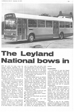
382 The Leyland National bows in
Page 141
Page 142
Page 144
Page 147
If you've noticed an error in this article please click here to report it so we can fix it.
OFF the secret list today comes the Leyland National single-deck bus, an example of which has been unveiled and put on public view at the Commercial Motor Show, Earls Court. This is the bus which will be built by the Leyland National Co Ltd, a company jointly owned by the National Bus Company and British Leyland, the setting-up of which was announced in July last year.
Production is due to start in late 1971 at a new plant under construction at Lillyhall, near Workington. Cumberland. with an output of 2000 vehicles a year at first. Initially, the Leyland National will be available to the UK market only.
Although the bus is to be built by the new Leyland National company, it has been designed and the prototypes tested at Leyland Motors' factory in Leyland, Lancashire. by a special design team. Never before, says Leyland, has a British manufacturer put so much effort, expertise and expenditure into developing a single range of buses.
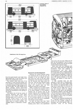
Basically the bus is a fully integrated structure designed to be particularly resistant to side-swipe, rollover and extensive collapse on impact. It is available in two basic lengths-10.3 metres (33.8ft.) and 11.3 metres (37ft.), and with a wide front entrance/exit, or wide front entrance and separate wide central exit. The shorter version can carry up to 40 seated passengers (two doorways) or 44 passengers (one door), while the longer version seats up to 48 passengers (two doorways) or 52 passengers (one door).
Alternative seating layouts are optional, as are colour of trim, exterior colour scheme, number and position of destination indicators, and the operator's choice of ticket equipment. Beyond this point, design features are standardized, with no options—this allows for common and interchangeable components to be used, simplifying initial construction, subsequent maintenance, or repair.
Four common areas are built into each bus, irrespective of length. These are: • Front end including driver's cornpartment and front axle.
• Centre door (when fitted), rear axle and power pack.
• The extreme rear end with cooling /heating equipment.
• Pillar and roof stick—"ring framing". Consequently only the panels between the frames are not interchangeable. They are, however, the cheapest and easiest to produce.
Construction It is interesting to note that integral construction, not generally favoured by many British operators, was chosen by Leyland because conventional construction methods where the chassis and body are designed and produced separately were considered by the design team to be unsafe—such buses were structurally unsound, they felt. In addition they were expensive to produce because of the high labour content and lack of component standardization.
The body and underframe structure is built as a complete unit. The underframe is largely built-up from varying sizes of channel of 15 ton /in2 yield steel with pressed steel cross-members in the suspension areas and pressed steel wheel arch risers. Side framing employs formed longitudinal members with pressed steel door frames and areas adjacent to wheel arches and doors reinforced by steel truss panels.
Riveting is used for the assembly, although sub-assemblies are welded. Areas likely to be easily damaged are free from welding. Exterior panelling is of steel, apart from the panels beneath waist height where high-strength alloy is used; the exterior roof panel is one complete alloy section.
The roofstick which forms part of the ring frame is a main structural member, and is an assembly of substantial depth forming a transverse member of high strength at the top of the pillar. The stick consists of two pierced pressings secured back-to-back along the line of abutment of the flanges and around the circumference of the openings in the member.
The interior trim of the bus consists of coloured decorative hard faced plastic laminate with hidden fixings. These trimming panels can be removed in a few seconds, giving access to the body framework and the closely spaced rivets which secure all exterior panelling. This simplifies repairs or maintenance considerably. Research and development Although the Leyland National venture was announced only in July last year, the conception of the new integral bus dates back about four years. In the early stages development work took place on mock-ups, and the full-scale work began about two years ago. There has been extensive testing over the past 18 months, and a special design and research team has been employed exclusively on this project.
While a complete bus is on show at Earls Court, the research and evaluation work is by no means finished. It is the company's intention that all proving work on the Leyland National will be completed before the bus is offered for sale. Too often in the past much of the "proving" has been done by the unwitting operator, on a trial and error basis, and at the cost of unreliability and shortage of spare vehicles.
To date, the buses have been "hand built" models, subjected to intensive tests to breaking point, both in the experimental shops and on the test track. When the LN goes into full production it will, of course, be jig-built. Jig-built buses will also be tested severely before production begins.
Much static work was conducted with joints, such as pillar/waist rail or pillar /floor attachments. These were subjected to two-dimensional and later threedimensional tests. Then a computer analysis of a module (full bay) was conducted and a computer program established. A check-out of the computer was then made. There are about 400 separate elements in the body structure, and analysis of these parts is continuing.
A fully assembled body was then subjected to stress tests to breaking point, the readings from the stress gauges being fully analysed. An important .factor at this stage was to ensure that, if, in the event of an accident the bus rolled over on to its roof, the structure would not collapse. Attention was also paid to the elimination of progressive collapse of the body should a bus be involved in a head-on collision or be struck from behind. Even the seats have been designed in such a way as to prevent their collapse on impact.
Work was also conducted simultaneously on a full-scale mock-up of the bus to provide the best possible conditions for passengers and driver /operator alike. An ergonomic study of the driving compartment was made, for example, with controls ideally placed to suit the 611. driver /operator or the 5ft. woman driver / operator equally well.
Positioning of seats, depth and position of windows (to suit both seated and standing passengers), location of steps, width of doorways, etc, have all been carefully studied.
Entrance to the bus is by a two-step entrance, and the design allows for a two-step exit where a central exit is fitted. Placing the exit as far back as possible (immediately ahead of the rear axle) means that the majority of passengers negotiate only two steps when entering or leaving the bus. A further step behind the exit leads to the rear part of the saloon. All steps and floors are completely flat; ramps are eliminated entirely.
Aerodynamic styling
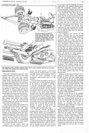
The lines of the Leyland National bus owe a lot to aerodynamics—probably the first time that this factor has been applied to a British bus. To begin with the bus was a rectangular box of the appropriate length (to scale), with a smaller box mounted on the rear. This latter box represented the pod mounted on the rear of the bus to house the heating and ventilation units.
The box was then subjected to aerodynamic tests and its shape modified in stages to achieve the best results; one factor was air flow through the engine.
It was found that the air displaced by the heater pod tended to re-attach itself to the body, and no fewer than 40 different pods were designed before the best shape was determined. The design team were not sure what effect the different lengths of the bus would have on the air flow, but in practice it was found that there was little difference between the 10and 11-metre buses.
Electrical system
A new, flat, 7-core wire, lin. wide and 3 /16in. thick and shaped to avoid incorrect plug assembly, has replaced the traditional colour-coded separate wires bound together. The new wire has an adhesive backing and can easily be fixed between trim and body panels. Colour-coded harnesses have been retained in those areas where individual connections to components are required.
To facilitate maintenance and servicing the wiring is in lengths, plugged at each end so that if a fault is traced to one area the electrician simply unplugs the section and replaces it with another. A test panel has been designed which can be plugged into the control panel for tracing and diagnosing faults.
The control panel itself is divided into sections with each section connected into the circuit by multiple-pin plugs. Consequently rapid replacement of faulty components can be achieved.
Driving environment
Extensive ergonomic studies were carried out to produce a driving compartment well suited to 95 per cent of possible "driver statures"—male or female. The control area is standard, irrespective of overall length or number of doors.
The controls are divided into four categories, according to priority. They are as follows: • Driving controls (wipers, washers, horn, direction indicators, side and head lights, etc).
• Prepare-to-drive controls (gear selector, parking brake, master stop/start switch, etc).
• Fare collection.
• Passenger environment controls (interior lighting, heating, and so on).
The central instrument is a 140mm dia speedometer or tachograph ffanked on one side by a dual air gauge of 80mm dia and on the other by either an 80mm dia tachometer or a combination of any two other instruments mounted onto one 80mm dia uOt. For example, fuel gauge and ammeter.
In addition the panel incorporates a system of warning_lights separated into three groups: • Indication (trafllcators, main beam, parking brake, etc).
• Warning faults which the driver must report on return to base (brake lining change, non charging, etc).
• Danger faults which must receiveimmediate attention (low water, no air pressure, high water temperature, oil pressure, etc.)
An area on the left of the driving compartment has been left completely clear to cater for customer's fare collection equipment. The main mechanical components in the Leyland National bus fall into three main sections—the front axle and steering assembly, the rear axle assembly and the "power pack". Running units are mounted directly to the integral body and sub-frame, the engine being a horizontal version of the fixed-head Leyland 500 Series and mounted as a unit with the gearbox. The drive from the gearbox is taken forward through the axle casing to primary-reduction gearing mounted at the front of the final drive casing which houses the secondary gearing.
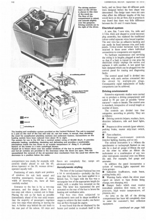
Air suspension is fitted all round and the steering mechanism represents a considerable change from current heavy-vehicle practice. It is of the power-assisted rack-and-pinion type with the rack mounted transversely on the axle beam.
Only one basic engine will be fitted in the bus. This will be the Leyland 510 which is a turbocharged version of the 500. Three power-output variations will be available, each of them representing a considerable derating on the maximum power this unit is capable of producing. Lowest output will be 150 bhp at 2,000 rpm and the intermediate figure is 180 bhp at 2,000 rpm.Top output is 200 bhp at 2,200 rpm. Corresponding maximum torque figures at these settings have not been released by Leyland.
Control of the engine from the accelerator pedal is through an air-pressure system. The pedal operates a valve which controls the air pressure supply to a small actuathig cylinder at the fuel pump. There is a total of 1.75in. movement at the accelerator, which requires from 4 to 101b pressure.
The drive from the engine to the four; or five-speed semior fully-automatic gearbox to be offered in the design is through a 17.75in.-dia "charged-fluid coupling". This is basically a normal fluid coupling as used with epicyclic gearboxes but the coupling and gearbox share the same oil. There is an oil pump in the casing which feeds oil through a filter into the coupling, whence it returns to the gearbox through the centre of the mainshaft. As well as reducing sealing problems at the coupling the design has the advantages that there is improved cooling of the coupling at low road speeds (through the greater mass of oil) and that the oil in the gearbox is cooled at high speed; the coupling is finned and acts as a heat exchanger when running at high rpm.
To overcome possible problems in propeller-shaft design with rear longitudinally located engines, the transmission is taken to the front end of the new-design rear axle, actually going through the casing to a helical-gearing primary reduction assembly which is integral with the nose of the differential and final drive casing. The final spiral-bevel gearing has a ratio of 3.08 to 1 and by selecting one of three sets of gears for the primary reduction, overall ratios of 4.3, 4.9 and 5.7 can be obtained. The crown wheel itself is 181n. diameter which is larger than the component currently used on Leyland passenger vehicles; this is to take care of the high torque output of the 510.
Air suspension units fitted are of the low-frequency type using the rolling-lobe system and this is said to give improved ride and handling compared with current types available. At the rear there is an A frame with only three moving connections, one on the apex and one at each end of the Panhard rod used for lateral location. There is also a Panhard rod at the front suspension; the axle is located also by deep and thin leading-arms which serve to restrict roll. At both the front and rear there are telescopic dampers.
Air suspension was chosen for the Leyland National bus for the normal reasons of constant floor height irrespective of load and improved ride. In this application there is a softer ride than on existing Leyland designs, and there is 7.5in. total movement between bump and rebound, which is more than usual for a British vehicle. The layout is simple as there are only four air springs. Having the rear springs behind the wheels allows the longest possible Iow-flOor level and the advantage of having the springs as widely spaced as practicable keeps roll to a minimum.
The use of a steering layout in which the rack for the power-assisted steering is mounted directly on the axle is said to promote precise handling and at the same time act as an efficient damper to the steering movement. The Adwest steering unit is rubber-mounted to the axle so that it is not affected by axle twist. To move the front wheels from full lock on one side to full lock on the other requires five turns of the steering wheel.
Braking on the Leyland National bus is through a full-air system with separate circuits for front and rear. Spring brake units are fitted at the rear axle for parking and all brake units incorporate SAB slack adjusters to maintain peak efficiency. Drum diameter is 15.5in. all round with 6in. wide shoes at the front and 8in. wide at the rear giving a total brake lining area of 776 sq.in. The system is designed to give more than the legal brake efficiency requirements for passenger-vehicle application.
Wheels on the bus are of the standard type but a new design of tyre is fitted. Tyre equipment is 11/70 (10.9)-22.5 LP tubeless. They are "squatter" than normal for a 22.5in. size, having the low aspect ratio of 70 per cent. The new tyre is 38in. in diameter as compared with 42in. for conventional tyres, allowing an important reduction in wheel box height.
The radiator for the cooling system of the engine is mounted at the rear of the body and the fan belt is driven by an extension shaft from the engine. The 24V electrical system of the bus incorporates a 100amp. alternator, batteries being located at the offside rear and carried in a cradle which swings about its centre for access. It is estimated that swept circles of the Leyland National bus will be 65ft. for the 10.3 metre overall length and 71ft. for the 11.3 metre design.