


Pressure Distributor . .546,630
Page 36
If you've noticed an error in this article please click here to report it so we can fix it.
to Actuate Injector
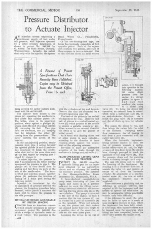
AN injection system employing a continuous supply of fuel under full pressure, with injectors operated by a timed pressure distributor, is shown in patent No. 546,598 by G. Amery, Tat Bank House, Oldbury, Worcestershire. Actually, the patent deals only with the injector, the system
being covered by earlier patents numbered 448,124 and 501,682.
The injector body houses a free piston (4) operating the needle-valve. and above this another piston (3). The latter, when in its uppermost position, abuts against a plunger (6) which closes the end of a small conduit (7) conveying the fuel. Two pipe lines are necessary, one (I) carrying fuel for injection, the other (5) coming from the pressure-timer. The latter controls the action of the injector.
In the non-injecting position, steady pressure from pipe. 5 acting between the opposed pistons (3 and 4) performs two functions: It holds the needlevalve shut and at the same time seals eff the fuel supply by keeping port 7 closed by plunger 6.
To cause injection, the pressure in pipe 5 is released by the timer, leaving
• unopposed the pressure in pipe 1. The plunger (6) is then forced from its seating and fuel flows via ports at the side to the needle-valve. The latter is lifted and injection occurs. Another piston (2) performs the function of sealing off a drain port during the injection period.
Injection is terminated by the re-application of pressure between the pistons, the foregoing procedure being reversed, whilst piston 2 uncovers the drain port to relieve the pressure in the side passages.
HYDRAULIC BRAKE ADJUSTABLE BY PISTON SPACING
COMING from an American concern which usually specializes in railway equipment, patent No. 546,591 describes a design of hydraulic brake for a road vehicle, The patentee is the
Budd Wheel Co., Philadelphia, Pennsylvania.
Of the two-floating-shoe type, the brake has hydraulic expanders at two opposite points. Each of the expanders contains two pistons, and each of these engages in turn a shoe-end. One of the sketches shows an axial section with the the cylinders at top and bottom. Observe that they are connected by a pressure-equalizing pipe (3).
The basis of the patent is the method of adjustment for wear. Between each pair of pistons is a conical-headed setscrew (2) which projects to the outside to receive a suitable wrench or key. When screwed in an outward direction the effect is to give the pistons an initial spread.
As is usual with floating shoes, one or other piston in each cylinder— according to the direction of drum rotation—abuts against the conical head of the adjusting setscrew.
Provision is made or alternative actuation of the brake through the medium of a linkage and pull-cable (1).-'
FLUID-OPERATED LIFTING GEAR FOR LAND TRACTOR
PATENT No, 596,650 . describes hydraulic lifting gear for an implement attached to an agricultural ti'a.ctor and an oil-pump for creating the necessary pressure. The patentee is the Minneapolis-Moline Power Implement C.o., Minneapolis, U.S.A.
A two-cylindered camshaft-driven pump takes lubricating oil from the engine and raises it .to a pressure sufficient to work the lifting tackle. Being a sectional elevation, the accompanying drawing shows only one of the two cylinders. The pump is attached to the side of the engine, in such a position that its two rockers (1) can be worked by a pair of eccentrics (8) on the camshaft. When not actually in use, the pistons and their rockers can descend under their own weight to a position clear of the eccentrics, so that no idle wear takes place.
Assuming the device to be out of action, it is brought into operation in the' following manner: Oil under slight pressure from the engine i s always preee.nt in space 5, but can reach nowhere else owing to a closed plug valve (6) To bring the device into operation., an external lever is moved, which turns a half-round cam (3), in an anti-clockwise direction. As a result the plug valve (6) is unseated and the oil floeirs up into the cylinder This causes the piston to rise, and thus brings the rocker into the orbit of the eccentric. Pumping action then commences, the oil making its exit from a port connected with the outlet' ball-valve (2).
When the hydraulic implementlifting cylinder reaches its limit, the rise of pressure unseats a springloaded safety-valve (4) and the highpressure oil then aows down the central bore, through passages' to reach the underside of the plug valve (6), This the pressure closes and the pumping action is thereby brought to a stop-.
The cam (3) serves aleo to control the lowering of the implement. By rotating it in a clockwise direction, it Unseats the valve (9) and permits an escape of oil from the hydraulic cylinder. By adjustment of a knurledheaded screw (9), the rate at which the implement descends can be regulated.
There does seem a possibility that the difference in pressure between that required to lift the implement and that needed to operate the relief-valve (4) may be arrangeable within practicable bounds, only with difficulty.
If the difference be small, the valve may be liable to open as a result of some incidental increase in load, before the implement has been fully raised. If it be large, then excessive stress may he imposed upon the apparatus, when lifting has been completed., before the relief valve permits the escape of oil.