


A Compact Pumping Unit for Tippers
Page 60
If you've noticed an error in this article please click here to report it so we can fix it.
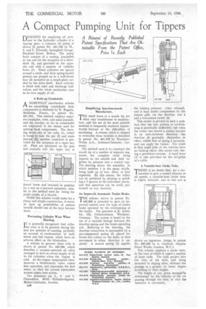
DESIGNED for supplying oil piessure to the hydraulic cylinder of a, tipping gear,. a compact MI pump is shown Ihpatent No. 451,748 by H., S. and F. Edwards, Springfield Garage, Bradford. Street, Bolton. The pump body consists Of a casting, journalled at one end for the reception of a driveshaft (3), and provided at the opposite end with .a .number of cylinder bores (1). These cylinders are spaced around a circle, and their spring-loaded pistons. are pressed on to a ball-thrust race (2) mounted on a awash-plate carried by the drive shaft. Each cylinder is fitted with inlet and discharge ballvalves, and the whole mechanism runs in its own supply of oil.
A Built-up Crankshaft.
ASOMEWHAT unorthodox schenie for; assembling crankshafts from components is disclosed by E. Bugatti, Molsheim, France, in patent No. 451,753-. .This method employs separate crankpins, webs, and main journals, and the noyelty, so far as crankshafts are concerned, is the means used for uniting these components. The drawing shows one of the webs (1), whith is bored to take the pin (2) and main journal (3); another cross-hole is provided for the reception of a taper key (4). Flats are machined on the pins and journals„ and the taper key is
forced home and retained in position by a nut on a screwed extension, similar to the method used for fixing the pedal cranks of a bicycle. Whilst this scheme would make for a cheap and simple construction, it seems to open up possibilities of serious trouble should one of the keys become loose. ....
Preventing Cylinder Wear When Starting.
I T is generally recognized that cylin der wear is at its greatest during the first few minutes of running, probably on account of condensation of both steam and fuel vapour, which have an adverse effect on the lubrication.
A scheme to prevent these evils is shown in patent No. 450,290, which describes a vacuum-operated oil valve arranged to feed an excess supply of oil to the cylinders when the engine is cold. As the engine temperature rises, however, a thermostatic valve comes into operation, and supersedes the first valve, so that the normal' lubrication system comes into action.
The patentees. are J.-, C. and S. Clerneritson, 50-52 I-Calksbrothgatan, Malmo-Limhamn, Sweden.
B48
Simplifying Injection-nozzle , Manufacture.
THE small bores in a nozzle tip are I often very troublesome to manufacture, and the use of the most suitable material is frequently rendered impracticable because of the difficulties of machining. A scheme which is claimed to overcome these troubles is described in patent No. 451,729 by WandererWerke A.G., _Schonau-Chemnitz, Germany.
The method used is to construct the nozzle tip of a number of separate segments, the' complete circle being tapered on the outside and held together by pressure into a conical cup. The drawing shows the assembly, in which member 1 is the spray nozzle, being built up of two, three, or four segments. By, this means, the orifice can be produced' by planing or grinding a V-groove in the individual pieces, and this operation can be easily performed on any material.
An Improved Automatic Trailer Brake.
THE scheme shown in patent No. 450,500 is intended to give an improved control over the type of trailer brake operated by the overrunning of the trailer. The patentee is K. Schreter, 122, Gothaerstrasse, Wechniar, Germany. The system is based on the use of a variable linkage between the drawbar spring and the brake-operating rod. Referring to the drawing, the drawbar connection is surrounded by a pre-compressed spring (5) placed between two collars on the shaft, so that movement in either direction is opposed. A second spring (2) applies
the braking pressure, when released, and is kept under compression by the tractor pull, via the drawbar, rod 4 and a two-armed rocker (3).
This rocker is pivoted in such a position that the first portion of overrunning is practically ineffective; but when the rocker has moved a certain 'amount in an anti-clockwise direction ,,the drawbar (5) gradually diminishes in effect, whilst that of spring 2 increases, and can apply the brakes. The result is that small jolts of the vehicles have no braking effect; this occurs only during a persistent Overrun. A hand lever (1) is also provided for the reception of a cable.
A Variable-bore Choke Tube.
THERE is no doubt that, for a carburetter to give a correct nitxture at all speeds, a variable-bore choke tube is highly desirable, and to this end is
shown an ingenious design in patent No. 450,495 by A. Gladwell, Ampton Street Works, London, W.C.1.
This scheme employs a choke tube, in the bore of which is caged a number of loose balls. The balls project into the bore of the tube, and being mounted in sloping slots, obstruct the passage in a greater or lesser degree according to their height.
The height at any given monientehis determined by the velocity of the • air, passing through the tube, so that the variation is automatic.