


Patents Completed.
Page 22
If you've noticed an error in this article please click here to report it so we can fix it.
Leyland and Garrett Axles. L.G.O.C. Bodywork. Wolseley Engine Construction.
Bridged Rear-axles.
B. Spurrier, No 20,139, dated 4th September, 1912.—This invention consists in forming an axle of increased strength which is specially applicable to
heavy motors. Instead of forming a bridge-piece in a horizontal plane, a bridge is formed in a vertical plane which is much more capable of sustaining a heavy weight, and materially stiffens and strengthens the axle to bear weight placed
above it.. The accompanying illustration shows one mode of constructing an axle according to this invention, and it will be seen that the dead axle is connected at the bottom by a continuous bridge-piece, whereas at the top, two short members have their ends bolted respectively to the dead axle and the
differential-gear casing. These short members and the gear casing together thus form a continuous bridge-piece. This bridge allows ample space for accommodating the differential or other gear required to be carried on the rear axle.
Motor Omnibus Body.
A. Crane and the London General Omnibus Co., Ltd., No. 19,458, dated 24th August, 1912.—This invention comprises an improved form of body construction for motor omnibuses o enable a better seating accommodation inside the vehicle. ft is preferred to arranee the seats transversely and of the garden type as usually found on the tops of these vehicles. As generally cons ructece the bodies arc formed with inwardly pro.
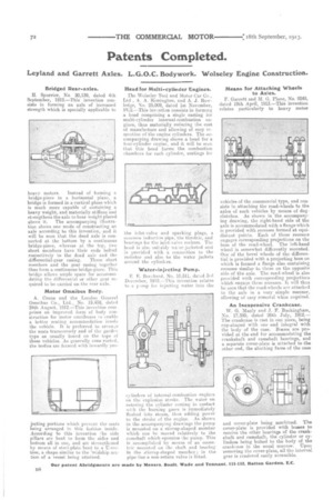
jecting portions which prevent the seats being arranged in this fashion inside. According to this invention I he side pillars are bent to form the sides and bottom all in one, and are strengthened by means of steel-plate bent to a 1J-section, a shape similar to the 'reidship section of a vessel being attained. Head for Multi-cylinder Engines.
The Wolseley Tool and Motor Car Co.,
Ltd , A. Remington, and A. J. Rowledge, No. 25,009, dated 1st November, 1912.—This inyentian consists in forming a head comprising a single casting for multi-cylinder internal-combustion engines, thus materially reducing the cost of manufacture and allowing of easy in. spection of the engine cylinders. The accompanying drawing shows a head for a four-cylinder engine, and it will be seen that this head forms the combustion chambers for each cylinder, seatings for
the inlet-valve and sparking plugs, a common inductiee pipe, the throttle, and hearings for the inlet-valve rockers. The head is also suitably wa:er-jacketed and is provided with a connection to the radiator and also to the water jackets around the cylinders.
Water-injecting Pump.
E E. Bernhard, No. 10,511, dated 3rd December, 1912.—This invention relates to a pump for injecting water into the cylinders of internal-combustion engines on the explosion stroke. The water on entering the cylinder coming in contact with the burning gases is immediately Flashed into steam, thus adding power to the stroke of the engine. As shown in the accompanying drawings the pump is mounted on a stirrup-shaped member which can be moved relatively to the camshaft which operates the pump. This is accomplished by means of an eccentric mounted on the shaft and bearing in the stirrup-shaped member; in the pipe-line a non-return valve is bteed. Means for Attaching Wheels to Axles.
F. Garrett and M. G. Plane, No. 9249, dated 19th April, 1913.—This invention relates particularly to heavy motor 'vehicles of the commercial type, and consists in attaching the road-wheels to the axles of such vehicles by means of dogclutches. As shown in the accompanying drawing, the right-hand side of the axle is accommodated with a flange which
provided with recesses formed at equidistant points. Each of these recesses engages corresponding projections on the boss of the road-wheel. The left-hand wheel is somewhat differently mounted. One of the bevel wheels of the differential is provided with a projecting boss on which is formed a flange also containing recesses similar to those on the opposite side of the axle. The road-wheel is also provided with corresponding projections which engage these recesses. It will thus be seen that the road-wheels are attached to the axle in a very simple manner, allowing of easy removal when required.
An Inexpensive Crankcase.
W. G. Manly and J. F. Buckingham, No. 17,380, dated 26th July, 1912.— The crankcase is cast in one piece, being cup-shaped with one end integral with the body of the case, BOSSE% are provided at the end for accommodating the crankshaft and camehaft bearings, and a separate cover-plate is attached to the other end, the abutting facee of the case
and cover-plate being machined. The cover-plate is provided with bosses to receive the other bearings of the crankshaft and camshaft, the cylinder or cylinders being bolted to the body of the crankcase in the usual manner. Upon removing the cover-plate, all the internal gear is rendered easily accessible.