


Design Improvements to
Page 80
If you've noticed an error in this article please click here to report it so we can fix it.
Mechanical Servo Brake Motors
L'ROM the Automotive Products Co., Ltd., and G. Gates, both of Brock House, Langham Street, London, W.1, comes patent No. 525,415, showing the latest progress in the design of frictionoperated servo-motors.
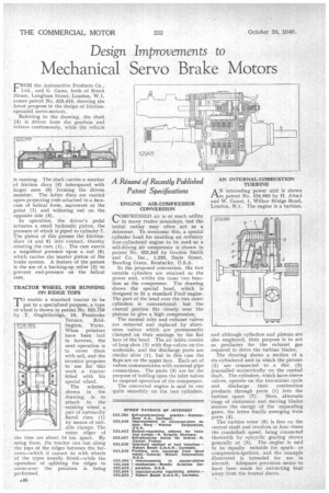
Referring to the drawing, the shaft (3) is driven from the gearbox and rotates continuously, while the vehicle is running. The shaft carries a number of friction discs (4) interspaced with larger ones (6) forming the driven member. The latter discs are carried upon projecting rods attached to a facecam of helical form, narrowest at the point (I) and widening out on the opposite side (5).
In operation, the driver's pedal actuates a small hydraulic piston, the pressure of which is piped to cylinder 7. The piston of this presses the frictiondiscs (4 and 6) into contact, thereby rotating the cam (1). The cam exerts a magnified pressure upon a rod (8) which carries the master piston of the brake system. A feature of the patent is the use of a backing-up roller (2) to prevent end-pressure on the helical cam.
TRACTOR WHEEL FOR RUNNING ON RIDGE TOPS TO enable a standard tractor to be • put to a specialized purpose, a type of wheel is shown in patent No. 525,753 by T. Oughtibridge, 19, Pembroke
Terrace, Bridlington, Yorks. When potatoes have been laid in furrows, the next operation is to cover them with soil, and the inventor proposes to use for this work a tractor fitted with his special wheel.
The scheme, shown in the drawing, is to attach to the existing wheel a pair of outwardly flared rims (1) by means of suitable clamps. The Outer edges of the rims are about 14 ins. apart. By using these, the tractor can run along the tops of the ridges between the furrows—which it cannot do with wheels of the types usually fitted—while the operation of splitting the ridges to cover-over the potatoes is being performed. ENGINE AIR-COMPRESSOR CONVERSION rOMPRESSED air is of much utility in many trades nowadays, but the initial outlay may often act as a deterrent. To overcome this, a special cylinder head for enabling an ordinary four-cylindered engine to be used as a self-drivng air compressor is shown in patent No, 525,345 by Gordon Smith and Co. Inc., 1,220, State Street, Bowling Green, Kentucky, U.S.A.
In the proposed conversion, the two outside cylinders are retained as the power unit, whilst the inner two function as the compressor. The drawing shows the special head, which is designed to fit a standard Ford engine. The part of the head over the two outer cylinders is conventional, but the central portion fits closely over the pistons to give a high compression.
The normal inlet and exhaust valves are removed and replaced by shortstem valves which are permanently clamped on their seatings by the flat face of the head. The air inlets consist of long slots (2) with flap-valves on the underside, and the discharge ports are similar slots (1), but in this case the flaps are on the upper face. Each set of valves communicates with external pipe connections. The parts (3) are for the purpose of holding open the inlet valves to suspend operation of the compressor. " The converted engine is said to run quite smoothly on the two cylinders. AN INTERNAL-COMBUSTION TURBINE
AN interesting power unit is shown in patent No, 524,993 by H. Attari and W. Gunst, 1, Willow Bridge Road, London, N.1. The engine is a turbine,
and although cylinders and pistons are also employed, their purpose is to act as producers for the exhaust gas required to drive the turbine blades.
The drawing shows a section of a six-cylindered unit in which the pistons (2) are connected to a disc (3) journalled eccentrically on the central shaft. The cylinders, which have sleeve valves, operate on the two-stroke cycle and discharge their combustion products through ports (1) into the turbine space (7). • Here, alternate rings of stationary and moving blades receive the energy of the expanding gases, the latter finally emerging from ports (4).
The turbine rotor (6) is free on the central shaft and revolves at four times the crankshaft speed, being connected therewith by epicyclic gearing shown generally at (5). The engine is said to be equally suitable for sparkor compression-ignition, and the example illustrated is intended for use in aircraft. Adequate provision seems to have been made for extracting heat away from the frosted sleeve.