


The Care and Maintenance of
Page 74

Page 77
If you've noticed an error in this article please click here to report it so we can fix it.
C.A.-V. Fuel-injection Equipment.
Expert Advice on a Matter of Vital Importance to All Operators of Oil-engined Vehicles Employing This Make
of Pump
ABSOLUTE cleanliness is an essential factor to ensure the efficient working of fuel-injection equipment, and it is therefore important that the bench on which any maintena:-.ce work or adjustments are to be made be kept scrupulously clean and free from all dirt, filings, etc., usually associated with engineering workshops. It is advisable to cover the bench with zinc sheeting or linoleum to facilitate cleaning, and to provide a number of small, clean containers to receive the various parts removed.
A thoroughly clean vessel fitted with a cover and containing fresh paraffin or oil fuel should also be available for washing the parts. The bench should be provided with a small vice, the jaws of which are protected with clean soft copper or zinc shields.
To produce the exceedingly fine _limits of accuracy between the injection-pump plunger and barrel, delivery valve and seating, nozzle body and valve, it is necessary to lap them together during manufacture, which makes it essential that these carefully mated parts should never be separated throughout their working life and should on no account be interchanged. Care should be taken, therefore, to segregate the complete assemblies when they are removed from the pump or nozzle holder, and replace them in the same order when reassembling. Never in any circumstances should they be treated with grinding or lapping compoqpds.
Adjustment of the Equipment
When an oil engine is received straight from the manufacturers it will be already correctly adjusted, but during overhaul attention should be paid to the• following -points before starting:—
(1) The nozzles must he thoroughly washed in clean paraffin or oil fuel and the joint faces of nozzles and holders cleaned. If necessary, the nozzles must then be adjusted afresh to the opening pressure required for the engine. Where engine makers do not specify the pressure setting it is recommended to use 1,500 lb. per sq. in. (100 atmos.) for all pintle nozzles, and 2,250 lb. per sq. in. (150 atmos.) for
multi-hole nozzles. This is done by means of the C.A.V. Nozzle Setting Outfit (Fig. 3). If one of these be not available, the nozzle holders may be connected to the pump by means of the delivery pipes, and the nozzles allowed to spray into the open so that their spraying qualities can be observed.
Beware of the Open Spray As a special precaution, in no circumstances allow the hand to come into contact with the spray in close proximity to the nozzle, as the working pressure will cause the oil to penetrate the skin with ease.
The adjusting screw (111k) on the nozzle holder should now be completely loosened and screwed in again until a slight resistance of the nozzle compres
sion spring can be noticed. After a further turn, the opening pressure is adjusted to approximately:—
(a) 1,200 lb. per sq. in. (80 atmos.) in pintle nozzles types SI and S3, with 1 and 1.5 mm. pintle diameter respectively.
(b) 1,000 lb. per sq. in. (65 atmos.) in pintle nozzles types 52, with 2 mm. pintle diameter.
(c) 750 lb, per sq. in. (50 atmos.) in one hole or multi-hole nozzles. For each further turn the increase in pressure is about:— • 1,000 lb. per sq. in. (65 atmos.) for (a); 750 lb. per sq. in. (50 atmos.) for (b); 750 lb. per sq. in. (50 atmos.) for (c).
Note.—This method of nozzle setting is approximate and should be employed only in emergency or where no nozzlesetting outfit is available.
Care in Fitting a Nozzle When fitting the nozzle into the cylinder head, see that it is not jammed when tightening down the holder, i.e., that the fixing nuts are uniformly tightened and that the joint washer which is enclosed with every nozzle is inserted between the holder and the cylinder cover.
(2) Pump and engine must be so adjusted relatively to each other that the injection begins at exactly the right moment. In order to achieve this, a mark is made on the pump end, whilst two marks, R and L, denoting commencement of delivery for clockwise and anti-clockwise rotation, are made on the driving coupling. When the first-mentioned mark and—according to the direction of rotation—the marks R or L coincide, the pump plunger nearest the coupling is adjusted to start injection. Then the engine piston corresponding to the pump plunger adjusted to the beginning of injection, is brought into the position before top dead centre at which the fuel is to be injected; the engine and fuel pump are then coupled together in this position. The coupling halves and the special fibre disc should then be assembled together so that the zeros on 'these three parts will now coincide. After the above preliminary adjustment has been made, the final adjustment can be effected, this being facilitated by the lines provided on the coupling (1 graduation = 3 degrees on the cam shaft). The suction pipe can then be cleaned and connected.
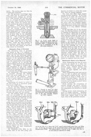
• (3) The 'governor (centrifugal type only) must now be connected to the accelerator-pedal linkage by moving lever 110p towards the full-load position, i.e., towards the pump, until the control rod (107d) touches the stop in sleeve 101m (when the control rod is in this position the pump is adjusted to full output). Then move lever 110p farther forward in the same direction until the no-load springs of the governor are compressed by the amount of the idling path, i.e., until a considerable resistance is felt. Limit this position of lever 110p by the adjustable stop (110ma) on the governor housing (Fig. 5). The accelerator pedal can then be brought into the full-loatl position and the gear connected to the lever 110p, when this is in the final position. Limit the final position of the accelerator pedal itself in such a way that the stop 110ma of the lever 110p cannot be overloaded.
Alternative Form of Governor The alternative form of governor stop shown in Fig. 4 is adjusted in exactly the same manner for maximum speed, but by the additional adjustment of the threaded sleeve (210b) the pressure of the spring-loaded plunger (210a) can be varied in order to overcome the control-pedal return spring in such a position as to provide the required idling speed for any particular engine. The engine is stopped by a final movement of the pawl (210d) usually effected by lifting the control • pedal and so exerting sufficient pressure to overcome the plunger.
(9) Lubrication.—The pump should be provided (through the dipstick hole) with good engine oil up to the level mark on the dipstick. About pint of good engine oil should also be put into the governor through the flap oiler.
Lubricating oil should be added to the fuel pump up to maximum gauge level every 1,000 miles.
(5) Air Venting.—Before the engine is started, also when refilling the tank after it has been inadvertently emptied, set that there is no air in the system between the tank and the nozzles:' (a) The feeding pump and oil-fuel filter are air-vented by the air-vent screw on the filter being opened and the engine being turned until the oil fuel pours out free from air bubbles.
.:(13) The suction chamber of the fuel pump can be air-vented by first loosening the closing plug and filling the filter with oil fuel after removing the closing plug. The oil should then be allowed to flow until it issues from the closing plag free from bubbles. The pump barrel is air-vented by first giving the pump a few turns with the control rod in the " stop " position, after which the .oil is allowed to flow in while the turning is continued, until it leaves the open-delivery stud free from bubbles.
(c) The delivery pipes are air-vented by the union connection of the delivery pipe on the nozzle-holder stud being loosened and the engine turned untiloil fuel appears free from bubbles; the delivery pipes are then immediately connected up again.
(6) Filtration.—The filter in the suction inlet of the feed pump (the' function of which is to retain the coarse dirt) must be cleaned regularly.
The main fuel filter must receive careful periodic attention. If the filter element be of cloth, the cloth 'should be inspected weekly for punctures or excess dirt, and replaced if necessary. The cost of a filter cloth amounts to a few pence only and complete replacement after two to three weeks' running (depending upon the type and extent of service) is a very definite ultimate economy.
If the fuel filter be of the felt-pad type, the filtering element will respond to cleaning by immersion in clean oil fuel or petrol. Both ends of the filter pack should be closed by corks, one of which should carry a bicycle valve to permit the passage of compressed air (either from main supply or from hand pump). As the air passes from the inside to the outside of the pads, all dirt is carried away and can be rinsed off by the cleaning oil. It is not sufficient merely to rinse the felt pack or brush it in the fuel, as this may cause the dirt removed to settle on the inside and subsequently pass into the injection system when the filter is replaced on the engine. The life of a felt pack is limited usually to about nine to 12, months, when the pads should be replaced from new stock.
Maintenance Points to be Observed When dismantling see that all parts removed are placed in a clean dry place. Parts which are mated in production (e.g., element plunger and barrel, delivery valve and seating) should be kept together and never interchanged.
When reassembling wash each part in clean oil fuel or petrol and assemble moving parts without drying. Do not wipe parts on damp or fluffy cloth or handle with moist fingers. See that all screws, sealing wires and splitpins fit correctly and arefirmly secured before passing the assembly.
Never attempt the reclamation of element plunger and barrel, delivery valve or nozzle by stoning or treating the components with abrasives or metal During service cheek lubricating 'oil levels at weekly intervals. Examine filter every two to three weeks; if of the cloth type, replace cloth; if the felt type, clean in the prescribed manner. .