


UNUSUAL, TRACTOR DESIGN.
Page 64
If you've noticed an error in this article please click here to report it so we can fix it.
A Resum6 of Recently Published Patents.
TO arrange a tractor so that the two rear wheels are not strictly in line with one another is a proceeding which, although not sufficiently important to justify the term revolutionary, is still sufficiently of thef way to-, attract enough notice and to make it worth while to investigate the originating circumstances. Such a machine is described by IL Partridge in specification No. 168,346. The objects at which this inventor aims are stated to be those of providing gearing of extreme simplicity and sturdiness, which will effect great economy of power, will be wear-compensating, and not easily deranged or liable teelamage as the result of dust and dirt, which are the natural environments in which a tractor is normally employed.
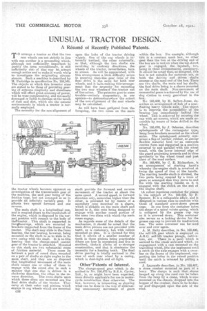
The necessity for the non-alignment of the tractor wheels becomes apparent on investigation of the transmission gear of the machine, the said gear being of the friction type, but not arranged so as to provide an infinitely variable gear. It affords two speeds forward and one reverse.
The main, shaft is a longitudinal one, and is coupled direct to the.crankshaft of the engine, which is-disposed in the normal position with respect to the body of theTtractor. This shaft is supported in twoothea.rings, which are mounted in brackets supported from the frame of the tractor. The shaft may slide in the front bearing, the rear bearing, however, being mounted on the shaft so as to slide in its own casing with the shaft. It is to. this bearing that the change-speed control gear of the tractors attached. Mounted on this shaft are two substantial cones of friction material. These cones lie between a pair of coned discs mounted on a pair of shafts at right angles to the main shaft, and they are so disposed that longitudinal movement of the main shaft causes one or other of them to engage with the coned disc in such a manner that one disc is driven in a clockwise direction, the other in the re verse direction. The cross-shafts upon which these discs are mounte.d ere the final drive shafts of the tractor. They carry at their outer end pinions which engage in cog wheels which are mounted upon the hubs of the tractor driving wheels. One of the cog wheels is internally toothed, the other externally, so that, although the two shafts are revolving in contrary directions, the wheels of the tractor, nevertheless, turn in unison. As will be appreciated, with this arrangement a little difficulty arises in ensuring that.the. gear ratio of the final drive is thG same for both rear wheels, and it isiinenaking this.arrangemeet that the neeessity for mounting the two rear wheelseof the, tractor out of line-arises. Thepatentee goes to some trouble—entirely unnecestary, in our opinion—to demon.strateehow the extent of the non-alignment of the rear wheels may be calculated.
As will have been gathered from the foregoing, the two cones on the. main
shaft provide for forward and reverse movement of the tractor at about the same speed. A second speed, in forward direction only, somewhat higher than the other, is provided for by means of secondary COne mounted on a sleeve, which is elidable on the main shaft and keyed to it, this cone being designed to engage with another coned portion of the same two discs with which thie main cones engage.
As regards some of the details of the mechanism, it should be noted that the main drive pinions are net provided with teeth, as is customary, but with rollers mounted on pins. It is claimed for this that it allows of a smaller number of teeth in these pinions being practicable (there are four in ones pinion and five in another), thateit allows of a. stronger construction, and that it eliminates the necessity for a hunting tooth. The final drive gearing is totally enclosed in the case of each rear wheel by a casing, which is dust-tight and oil-tight.
OtberTatents of Interest.
The change-speed gear. which is, de. scribed in No. 168,475 by B.S.A. Cycles, Ltd., is, as might have been expected, more directly applicable for use in motorcycle construction than otherwise. The box, however, is interesting as showing what can be done in the way of eliminating unnecessary movement of gears
within the box. For example, although this is a constant mesh box, no other gear than the two at the driving end of the box are in motion when the top direct gear is engaged, the layshaft, too, being in these circumstances, stationary. It should be noted that, as designed, this box is not suitable for motorcar use, as both the driving and driven shafts emerge at the same end of the box. There are two shafts' the main and lay shafts, the final drive being to a.sleeve mounted on the main shaft. Notemeeenient of unessential gears is achieved by the use of dog cluthes to every gearwheel in the box.
No. 168,480, by H. Sefton-Jones, de scribes an arrangement of hub of a semifloating heavy vehicle axle. The object is to improve the accessibility of the bearing cap immediately behind the wheel. This is achieved by securing the cap with set-screws, which .are made aceessible by means of holes drilled, in the wheel.
No. 168,470, by J. Osborne, describes splashguards of the, rectangular type, hung from brackets mounted. on. the. wheel axles. The splashguard actually comprises a flap of leather, rubber, or similar flexible material bent to. an. outwards convex form and supported in a position external to and parallel with the wheel tread, with the lower internal edge of the guard projecting towards and in close woximity to the wheel tread and just clear of the road surface.
No..168,460, by C. E. Richardson, is an arrangement of starting hand'e whereby the.engine shaft is revolved at twice the speed of that of the handle. The starting handleehaft is-divided, the two parts being coupled by a train of gears so arranged that they move to and fro with the starting handle as it is engaged with the -clutch on the end of the engine shaft.
IA rather ingenious container for grease is the subject of No, 168,428, by P. Spencer. It is a collapsable affair, and is designed in various sizes to conform with those of standard. screw-down grease cups. In one form the container takes the shape of a spiral volute spring, which is collapsed by the grease cup cap as it is screwed down. This container also serves as a locking device for the grease cup cap to prevent its inadvertent loss. The same container can be, used over and over again.
A. M. Baily 'describes, in No. 168,400, the self-lift gear which is employed on A.B.C. self-lift tractor plough, cultivators, etc. There is a pawl which is secured to the crank axles and which, on engagement with a cam mounted on the travelling wheel, lifts the implement until a catch on the axle engages with e crossbar on the frame of the implement, supporting the latter in the raised position until the catch is released by pulling a cord.
J. Lea-re:1de describes, in No. 168,487, a stone crusher mounted as part of a lorry. The design is such that stones heap_ed up along the road can be taken from the heap by a. crane, which ie,also mounted on the chassis, dropped into the hopper of the crusher, there to be broken up and' disgorged' upon the side of the road.