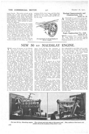
NEVI:r 50 H.P. MAUDSLAY ENGINE.
Page 58

If you've noticed an error in this article please click here to report it so we can fix it.
THE centre of interest on the Maudslay stand is the new 50 h.p. engine,.which is shown fitted in a 6-7 ton lorry chassis with double reduction drive and 14 ft. 6 in. wheelbase. The engine is an entirely new production. The cylinders, which measure 41 ins, bore by 6 ins, stroke, are cast together and crowned by a detachable: cylinder head cast in two parts, each part covering two cylinders. Bolted direct to the tops of the cylinders is the camshaft casing, the shaft itself running on three long bearings, which.are. lubricated from oil wells in the casing by ineanS of -loose rings, the oil being occasionally injected into the easing through ping Loles.
The casing is hinged to its supports at three points, and can be swung over to the off side of the motor to allow access to the two heads, each of which is held in position by means of 11 studs evenly disposed round the cylinder bare. The valves themselves are ,situated in the head, the exhaust seatings being water cooled and the inlets being located in detachable pockets. When these pockets are removed, the exhaust valves can he withdrawn through the inlet orifices. The valve springs are enclosed in an aluminium box situated below the camshaft casing, at the rear end of which is: the vertical bevel-driven shaft, which is, of cotirse, entirely. enclosed. The
upper bevel driving the camshaftis lubricated direct by an external pipe from the oil pump, the oil -returning to the crankcase through the ball and thrust bearings supporting the vertical shaft. A cross-drive is taken off the lower end of the shaft, -and drives the magneto on the offside and the water pump on the near side of the motor, altogether a very neat' lay-out.
The oil pump is driven by a bevel gear from the crankshaft, and runs submerged in the sump. It incorporates a filter, and can be removed as a complete unit by the unscrewing of five nuts. The MI is fed under pressure from the pump to the, main bearings, and thence through a drilled crankshaft to the .big. ends, from which it is taken through the hollow connecting rods to the small ends and fixed gudgeon pins. The castiron pistons are fitted with three rings above the gudgeon pins, their skirts being recessed and locking pins passing through the bosses.
The crankshaft runs on three whitemetal-lined beatings supported on extra strong housings, and at its forward end is fitted with a flat pulley, which drives the aluminium-bladed cooling fan through the medium of a belt, the tension of which can be varied by an adjustment to the eccentric fan bearing. The back of the gadiator is cowled, and
the undershield is provided with a number of louvres to increase the efficiency of the fan_ draught. The four arms of the crankcase rest, on an under frame whic-h also carries the gearbox. TheJ sump can be dropped separately to give access to the main bearing's, whilst the big-end bearings can be reached through the two pairs of large inspection doors, each held in position by a single thumb-nut situated one on either side of the case. The .pistons also can be withdrawn through these doors, leaving the cylinder block, which is attached to the top of the crankcase by 12 bolts, in position. In passing, it may be noted that the front and back of the cylinder block are covered by a: circular -alinninitun plate, an arrangement which should facilitate casting and the cleaning up of the inside of the water jackets. The exhaust pipe is taken away from the ports on the near side of the engine in a gentle forward sweep, whilst the inlet pipe is located an the off side and water warmed by a shunt from the main cooling system. The front cylinder relies. for its cooling on thermo-syphon circulation, the rest, of the cooling system consisting of a pipe from the radiator, which leads direct to the pump and a second pipe from the pump to the rear cylinder, the outlets being taken off the cylinder head.


