


COAL-GAS FOR MOTOR VEHICLES.*
Page 15
Page 16
If you've noticed an error in this article please click here to report it so we can fix it.
An Interesting and Valuable Paper by Mr. W. M. Barrett, of the Manchester Corporation.
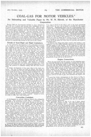
During 1915 the Government decided to place restrictions upon the use of petrol, and among other regulations the use of petrol was prohibited for char-a-hence work. This brought home to owners a realization of the stupendous demands upon our limited petrol supplies, and the necessity for securing a' lasting and efficient substitute. Coal-gas naturally was considered, but for some time the queetion of storage stood in the way of its application. To Mr. Barton, of &Teton, must be given the credit of providing a solution of the difficulty. It is worth noting that in his earliest experimente Mr. Barton used gas compressed in steel cylinders, but owing to difficulties experienced in breaking down the pressure he decided to store the gas in a flexible bag carried on the roof of the vehicle.
Details of Semi-Rigid and Rigid Containers.
A very interesting development is the semi-rigid container. A box made of + in. boards and strengthened with wrought iron brackets is fixed on the roof of the van. The length and width of this box depends upon the size of the van, but the heiedit of the sides is usually not less than 3 ft. 6 ins. The inside of the' box is ,lined with canvas, and painted successive coats of thick oil paint and shellac, one coat being allowed to dry before the next coat is applied. This renders the box perfectly gas tight. The top is cut out of the rubber fabric, with a rise in the centre of from 12 ins. to 18 ins,, and tide enough to allow, it. to slip over the outside edge of the box. It is then fastened with a continuous wooden lath . and screws to the top outside edge of the box, and the joint given a couple of coats of shellac. The result is a perfectly rigid and gas-tight base and sides, with a flexible top, which presents an extremely neat and workmanlike appearance even when the container is deflated—seeing that the sides remain rigid. r
A further development of the same idea is the rigid container. The box is' made and lined as before, and strips of wood or wrought iron are bent the desired shape and fastened ' to the inside of the' box, a distance apart of about 2 ft. The canvas top is then tightly stretched over the strips and fastened to the outside of the box, and over the canvas similar strips to those inside are fastened. The whole is then coated with shellac, the canvas being held rigidly between the inside and outside strips. The great advantage of this, type of container, apart from its neat appearance, is that the gee can be compressed within it, and I have personally seen such a container charged up to a pressure of 15 lb. per sq. in. This ,means that if the container will hola 300 cubic ft, at normal pressure, it will hold over 600 cubic ft, at 15 lb. pressure. I believe that if due consideration were given to the strength of materials employed, and to the method of bracing, a container such as I have described could be made to stand a pressure of 60 lb. per 'sq. in:, and then the vehicle would erun just four times as far as it would if the container was filled at normal pressure. A suggested improvement is that these containers should be made "torpedo" shaped in front, in order to offer less wind resistance.
Concertina Container.
A development on entirely different lines is the collapsable container. This container is made like a " concertina, and is guided in its downward travel, ,as the gas is used up, by flexible stays running on rigid guide rods fixed perpendicularly on the roof of the van, the guide rods being braced at the top in order to ensure rigidity. The top of the container is weighted with a thin sheet of metal, and as the gas is used up, the container folds up and eventually lies quite flat. This type, of container is recommended for private cars, where appearance is the first consideration, as by its-adoption the somewhat unsightly wooden superstructure is unnecessary, and it is impossible for the container to drop over the side.
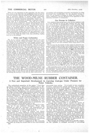
The method of filling these gas containers calls for some consideration. Fig. 1 shows what is, to my mind, a much, better way than those generally in vogue. You will see that a length of sheet-iron piping is perforated with +-in. hole and riveted to e 2-in, iron elbotv. This is inserted inside the bag, and the flexible trunk is tightly bound round it. A length of
2-in, pipe is fitted to the elbow, and at the most convenient spot a 2-in. by +-in. tee is fitted,' to provide for the engine connection. Immediately below the tee a back-pressure valve. is fitted, then a further length of pipe screwed at the end, with a 2-in, male gas thread. From the outlet of the tee +-in. iron pipe is run along the inside of the van, and a -h-in. plug cock fitted close to the drivers hand, continued with a length of flexible tube connected up to engine. The back-pressure valve is used in lieu of a plug cock. The head of the valve is light enough to. lift under a. gas pressure of 1 in, water column. When the valve is lifted off its seating the gas is allowed to pass through to the container, and immediately the pressure, is cut off at the main the valve falls by gravity and makes a gas-tight joint. If there is one thing more than another that strikes a gas engineer; it is the crude methods employed in connecting up . the gas supply to the engine. In the majority , of eases the engine induction pipe is drilled and tapped, and the only gas control is the plug tap fitted nearthe driver's hand, which, of course, is not sensitive enough to replete the volume of gas required at all engine speeds. In other words, it is impossible to keep a constantmixture of air and gas by this Means, and a constant mixture is an abeolute necessity to ensure even and economical running, the speed of the engine being controlled by varying the volume of the mixture' and not by ,varying the proportions of gas and air in the mixture.
Engine Connections.
When the gas is fed into the engine via the induction pipe, the butterfly throttle in the carburettor controls the air only, and when the accelerator pedal is depressed the mixture is weakened and the engine slows down, unless the engirie at the moment happens to the running -at a speed sufficient to draw in the extra volume of gas required to mix with the extra, volume of air admitted, or unless the driver, at the moment of depressing the accelerator pedal, opens the gas control cock. If he does so, he must, be careful to close it again when pulling, up with his clutch out, otherwese the mixture will be too rich in gas, and therefore the engine will
stop. • A somewhat better arrangement is that shown in Fig; 2.
In this case the carburetter is drilled and tapped just below the throttle, and' therefore there is some control of gas, apart from the gas control cock. It is, however, a wasteful method, and in order to prove whether any gas was blown back when the throttle was partly closed, I connected up a length of copper tube with' one of the air inlets on a Zenith carburetter. At the end of the copper tebe I fitted a wire gauze, and I was surprised to find that I could obtain a perfectly-aerated bunsen flame, which increased in size as the throttle was closing and disappea,riscl when the throttle was fully opened. This proved conclusively that more gas was being drawn from the container than the engine could deal with, and, therefore, my conclusion was that this method of connecting up was wasteful. It is true that, under certain conditions, either of these methods will give very fair results; but if the best results are only just good enough (and 1 submit that should be the aim of all motorists), then I recommend the use of a specially. designed coelegas carburetter. The apparatus shown in Fig. 3 is one I have tested
thoroughly with excellent results. You will notice that the gas enters at the bottom and is controlled by a 'butterfly throttle connected up to the accelerator pedal. After passing the throttle, the gas passes through the centre tube, the outlet of the tube being controlled by a steel ball making a gas-tight joint. Theeobject of the steel ball is to prevent inert gases or any products of combustion blowing back into the container, and to prevent automatically any waste of gas if the driver should forget to shut off his control cock when the . vehicle is standing. The air is admitted through revolving ,ports, the area of the air ports being worked out to' adinit the .maximum quantity of air required for complete combustion when the engine is runnilig all out and when the air ports are full open. The air port shutter is connected up to, and operated by the rod that controls the gas throttle, so that, after the correct mixture has once been obtained, and the relative position of the stir pert shutter permanently set, you can depend upon obtaining a mixture containing the' same proportions of air and gas at all engine speeds. There are two objections to this apparatus, the first being that, owing to the steel ball, the carburetter mast be fixed in a yertical position, and the secondis that the permanent setting is somewhat difficult to obtain without experience, although the second objection is more fancy than reality. If, however, an entirely automatic carburetter, wbich may be fitted in a horizontal position, if desired, is required, than the
design (Fig. 4) is recommended. You will see it closely follows the petrol carburettor, having interchangeable choke tubes and interchangeable gas nipples. In this design the air is drawn in through two permanently open Ports, but is choked down at the mixing point by the choke tube. The gas nipples are supplied drilled in various sizes, and to get the best results it 3s necessary to match a certain size of nipple with a certain size of Choke tube, just as is done now with petrol carburetters, excbpt that in the gas carburetter a further adjustment May be obtained by withdrawing the nipple a turn or two from the choke tube, thus admitting slightly more air to the mixture.
White and Poppe Carburetter.
Fig. 5 is a coal-gas carburetter, designed and put upon the market by Messrs. Wbite and Poppe. The most important feature of its construction is the throttle chamber, this being -made up of three parts, viz., the throttle chamber itself, an inside throttle and an outside throttle. The gas nipple is fixed permanently into the body of the "apparatus, over which is fitted the inside throttle. This throttle, when operated by the lever, closes the gas nipple; and, at the same time, closes the "air port. The outside throttle is used for adjustment purposes only, and provides suitable compensation for the varying quality of gas prevailing in different districts. In order to weaken or strengthen the gas it is necessary for the clamping nuts on the top of the Ehrottle chamber to -be slackened, when the cover can be moved slightly in an anti-clockwise direction to obtain a richer mixture ; or in clockwise direction for a weaker mixture. It will be seen that, by this arrangement, the closing of the gas nipple simultaneously closes the air port, and therefore a constant mixture of air and as is obtained at all engine speeds. Suitable stops are provided to allow of the inner throttle being closed entirely, or partly closed, according to the size of the engine, and deadslow running when in neutral while very quick acceleration is ensured. The whole apparatus is exceedingly simple, and operated by one lever only. I am inclined to think that still better results could be obtained by experimenting with superheating either or both the gas and air before carburation, or by -heating the mixture of gas and air after carburation. In gas-heating and gas-lighting apparatus superheating has been developedvery considerably. In one gas fired furnace I know of, the mixture is heated to about 150 degrees Fahr. before combustion, and the efficiency of the apparatus is considerably increased in consequence.
Gas Storage in Cylinders.
It is admitted that storing gas in the flexible container such as I have described is not an ideal method, but very much more could be done if manufacturers would co-operate with the gas undertakings and turn out a much better quality of fabric. It is really surprising the number of bags passing through my hands found ti3 be not gastight, and this, in in opinion, is entirely due to carelessness in manufacture. I think much better results could be obtained by the use of pure rubber insertioribetween two layers of fahrimather than the present method of spread-proofing the fabric. The time is coming when the Hackney Coach Committees throughout the country will insist upon the gas containers remaining gastight at a pressure of at least 6 in. water column before licensing the vehicles for public hire., and-therefore it is up to manufacturers to tackle this question energetically. There seems to be need for a public body to draw out a„specification of the material required, and to test each container before being fitted to the vehicles.
To overcome the drawbacks of what might be called the lowpressure system of gas storage, much attention has been given to the question of compressing gas at high pressure in cylinders. .It must be remembered that, altlinAgh the compression of gas is a well-understood business, an enTIVely new set of conditions arises when this method of storage is considered in relation to motor traction. In the first place, the weight and strength of the cylinder, the size of the cylinder, and the quantity of gas carried must be carefully considered. • Apparatus for reducing the pressure to a few tenths above atmosphere must be designed, and the effect of compression upon the calorific value of coal-gas must also be taken into consideration. Coal-gas is being regularly compressed in this country to a pressure of 120 atmospheres (about 1800 lb. per sq. in.), and this must be regarded as the maximum pressure -at which gas can he easily dealt with, although on the Continent pressures of over 3000 lb: per sq. in. are quite cornmon.
[The concluding-portion of Mr. Barrett's paper together with the illustrations to which reference is made will be published in our next issue. Therein Mr, Barrett makes a brief reference to the new Wood-Milne rubber cylinder for carrying coal-gas under pressure, of which full details are given in the following article.]