


Shorter Hydraulic Cylinder .
Page 94
If you've noticed an error in this article please click here to report it so we can fix it.
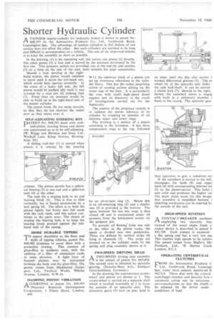
ATANDEM master-cylinder for hydraulic brakes is shown in patent No. 848,597 by the Automotive Products Co., Ltd., Tacbbrook Road, Leamington Spa. The advantage of tandem cylinders is that failure of one section does not affect the other, But such cylinders are inclined to be long and difficult to accommodate on a vehicle. The aim of the improved scheme is to keep the assembly as short as possible.
In the drawing, (1) is the operating rod; this moves one piston (2) directly. The other piston (3) is free and is moved by the pressure developed by the first one. Tiro pressure outlets are provided, one at the end (4) and another (5) on a boss on the side of the unit, both suitable for pipe connections.
Should a leak develop in the righthand system, the piston would continue to move until it meets the left-hand one, which would then operate normally, In
• the event of a leaky left side, the left piston would be .pushed idly until it was arrested by a stop pin. (6) striking face (7). From then on, pressure' would be able to build up in the right-hand side of .the master cylinder.
The piston lands (8) are made narrow, so that they do not obstruct the outlet port as they move over it.
SELF-ADJUSTING STEERING BOX IDATENT No. 848,592 deals with rack1 and-pinion steering boxes and shows one constructed so as to be self-adjusting. (W, Briggs and Burman and Sons, Ltd., Wychdll Lane, Kings Norton, Birmingham, 30.)
A sliding rack-bar (1) is moved when pinion 2 is rotated by the steering column. The pinion spindle has a spherical bearing (3) at one end and a spherical stub (4) at the other.
The stub fits a sloping hole in an end bearing block (5). This is free to aide vertically, but is biased downwards by a leaf spring (6). The effect is to hold the pinion lightly but firmly into full mesh with the rack teeth, and this action continues as the parts wear. The object of sloping the bearing hole is to keep the bearing block pressed against the lefthand wall of the casing.
MORE DURABLE TIPPERS ? impart durability to the floor and Pwalls of tipping vehicles, patent No. 849,982 proposes to cover them with a protective coating. This consists of glass-fibre in synthetic resin, with the addition of a filler of aluminium oxide to resist abrasion. A light layer of foamed plastics may be interposed between the body and the glass-fibre. The patent comes from Mickleover Transport, Ltd., Twyford Works, Whitby Avenue, London, N.W.10.
DAMPING PISTON VIBRATION A CCORDING to patent No. 846,995 1-1. (National Research Development Corporation, 1 Tilney Street, London,
B60 W.1), the sideways slack of a piston can set up transverse vibrations in the cylinder liners. This has the rather surprising action of causing serious pitting on the Water side of the ,liner. It is particularly the case with small high-speed diesel engines and its discovery is the result of investigations carried out for the Admiralty.
The essence of the proposed remedy is to cushion the piston sideways in its cylinder by trapping an annulus of oil between upper and lower rings.
The drawing is a section of a piston according to the invention. It has three compression rings at the top, followed by an oil-scraper ring (1). Below this is an oil-retaining ring (2) and a similar one (3) is provided at the bottom. The space between the last two rings is thus closed off and is maintained under oil pressure from the lubrication circuit via the gudgeon pin.
To prevent oil flowing from One side to the other as the piston rocks, the space is divided into two semicircles. These are defined by vertical strips (4) lying in channels (5). The strips are pressed on to the cylinder walls by the spring and plug assembly shown at 6.
TWO-SPEED DRIVING HEAD A TWO-SPEED driving axle assembly is the subject of patent No. 845,094. The second ratio is obtained by epicyclic gearing. (Daimler-Benz• A.G., Stuttgart Untertiirkheim, Germany.)
In the drawing the conventional crownwheel and pinion are shown at I. The crown-wheel is carried on a separate shell which is toothed internally at 2 to form the annulus of an epicyclic unit. The planetary gears (3) turn on pins held in an inner shell (4); this also carries t normal differential pinions (5). The su wheel (6) of the epicyclic unit slides the axle half-shaft. It can be moved a clutch fork (7). Moved to the right, shown, the sunwheel sleeve is engag with teeth in a stationary member I fixed to the casing. The epicyclic gear then operative to give a reduction rat
If the sunwheel is moved to the left, disengages the teeth (8) and engal teeth (6) with corresponding internal te( (9) on the planet-carrier. This locks I unit solid and produces the higher rat The main claim made for this design that assembly is simplified because 1 clutching mechanism can be inserted fn the outside of the unit.
HIGH-SPEED IGNITION
I—I A CONTACT-BREAKER mechani:
employing two movable Wm instead of the usual single blade a rocker device is described in patent Is 843,740. Each contact is mounted a flat spring and has a very low ma This enables high speeds to be achievt The patent comes from Mallory Me Products, Ltd., 78 Hatton Gard( London, E.C.1.
OPERATING CENTRIFUGAL CLUTCHES
FROM the Automotive Products C Ltd., Tachbrook Road, Leamingt Spa, come three patents numbered 84 942/3/4. These deal with the control centrifugal clutches and describe how I automatic action can be overcome servo-mechanism so •that the clutch c be released by the driver under conditions of load.