


A Double-chamber Combustion-head Design
Page 40
If you've noticed an error in this article please click here to report it so we can fix it.
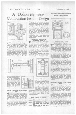
A Risurne of Recently Published Patent Specifications AN improvement in e design of
th
small compression-ignition engines comes in patent No. 512,823 from C. Chapman and F. Perkins, Ltd„ 17, Queen Street. Peterborough. This system employs two combustion chambers, one (3) being open to the cylinder, whilst the other (2) is formed as an ex-tension of the first one, being connected therewith by a comparatively narrow pgssage in which the injector (1) is placed. The first
chamber (3) is cylindrical the other being spherical.
On the cornpression stroke, the air swirls in opposite directions in the two chambers, and the fuel is injected in two streams,, one to each chamber. The direction of injection is the same as that of the air.
SIMPLE FIRE-PUMP CONVERSION • UNIT
AEANS for driving a pump, capable alof ready adaptation to an existing vehicle, is described in patent No. 512,909 by R. Palmer, of the Eagle Engineering Co., Ltd., Warwick. The chief advantage of the scheme is that there is no interference with the engine or transmission, the power for the pump being derived from frictional contact with one of the back wheels.
The drawing shows a rear view of the vehicle wheels and the pump drive.
£20
The pump (I) is bracketed on to the rear cross-member, and is driven via a universally jointed shaft (2) carrying a concave pulley (3). In operation, the pulley is pressed against the ',re by a clamping gear, and driven by the wheel which is jacked up for the purpose. When not required, the universal joint allows the shaft and pulley to be stowed away in an angular position, as shown in dotted lines. In combination with a tank wagon, the scheme provides a useful mobile firefighting outfit.
EFFICIENT COOLING OF INJECTION NOZZLES
T°prevent overheating of the injection nozzle is the object of a scheme shown in patent No. 512,114, by S. A. Adolphe Saurer, Arbon, Switzerland. Whilst the use of a copper sleeve around the injector is well known, according to the patent the benefits are nullified if the sleeve itself be subject to the hot gases, and the proposed design avoids this.
The nozzle is housed in a copper sleeVe (2), which is securely swaged into the cylinder head (3) and the
outer wall (6) of the casting, the intervening space (5) being occupied by the cooling water. An asbestos ring (4) limits the heat travel, the only portion of the injector subject to the full combustion temperature being the spray nose. The injector is held in position between a conical seat in the sleeve and an upper screw-plug (1), through which the fuel supply passes by way of a central duct.
A BRITISH COAL-DUST COMBUSTION SYSTEM
T"possibilities of using coal-dust as a fuel have for a long time been investigated in Germany, and now a British development comes to light in patent No. 512,936. The patentees are R. Fraser and the Buell Combustion Co., Ltd., 49, 11/loorgate, London, E.C.2. According to the -patent, one of the chief objections to the use of pulverized fuel is the extremely slow rate of combustion, and one of the aims of the invention is to eliminate this.
The general form of the engire is clearly shown in the drawing, the chief feature being the use of a refractory block (2) between the cylinder and the combustion chamber. This block is supported only by, thin webs (see plan view), so that its temperature may reach a working value of 600 degrees C. For starting purposes, it is proposed to pre-heat the block by means of an oil spray, not shown. The valve (1) is the admission control for the pulverized coal.
It is stated that the fuel used must be much finer than that hitherto employed, the particles not exceeding 10 microns in diameter. A micron is a thousandth part of a millimetre, or .00004 in.
IMPROVED DESIGN OF SCRAPER RING
AN oil-retaining piston ring which utilizes the blow-by of the combustion gases to assist in the return of excess oil is shown in patent No. 512,276, by J. W. Howlett and Wellworthy Piston Rings, Ltd., Lymington, lIants.
A section of the ring in place in the piston is shown in the drawing, but it should be noted that whilst the groove (3) extends completely around the periphery, the slits (1) are located only at intervals. The essence of the invention is that the upper portion (2) of the ring is of slightly smaller diameter than the rest, and it is this feature which causes the descending gases to help to blow the collected oil through the escape ports in the piston.