


THE CRAYMER UNLOADER.
Page 8
Page 9
If you've noticed an error in this article please click here to report it so we can fix it.
A Device 'Which Deals with One Ton Per Minute.
THE EFFICIENCY of motor road transport and its success as a rival. to other means of transport depends to a great extent upon the time factor; the time factor itself depends upon the average road ,speed and the time taken in loading and unloading the vehicle. Under the existing laws, the average road speed is limited, and improvement can only, he effected by shortening the
length of time required for taking up and distributing the basil. Thin time is at present considerable.
There are several more-or-less satisfactory methods of dealing with this problem, not so much for the loading as for the unloading. There is the ordinary tip wagon, by which the whole of the material can be unloaded in a fairly short time, but few of these wagons can actually tip the whole of the load without the assistance of manual labour and shovels.
. Attempts have also been made to produce a satisfaCtory body designed with several tipping compartments. This cer
tainly permits of partial distribution, but becomes .unduly complicated when many deliveries of specified quantities have to be made at different points. Efforts have else been made to produce a satisfactory loading and unloading device on the principle of the venetian blind, the blind roller being fixed close to the tailboard of the lorry. Unfortunately, althoughthe scheme was a very
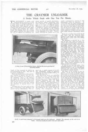
good one, a certain amount of trouble was experienced, owing to jamming, caused by the loose material working between the slats, etc. • An interesting device on somewhat similar lines to the venetian blind type of loader and unloacler, but of an improved type, is now being produced by Craymer Unloarters, Ltd., 97, High Street, Peckham, London, S.E. With this device the venetian blind platform is dispensed with and replaced by a number of plates counected together by pivoted tie-bars; these plates fold up on the tailboard of the vehicle during unloading. The arrangement will be readily understood by referring to the
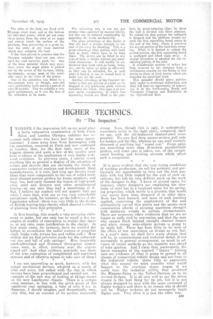
photographs which we reproduce. It will be seen that the plates emerge from the lorry in a practieally horizontal poeition, but when each plate is about halfway (rat it pivots on its tie-bar and assumes a slanting position until, as the action continues, it folds down on -to the plate which emerged immediately before it.
Hooks are provided close to the top of each plate, and the following plate catches on and hangs from these hooks. The last plate carries with it the .slitling back-board.
The platform is operated by a wire rope at each side; these are firmly secured to the innermost plate, and each of them passes round a pulley situated in a convenient position under the body. Each pulley carries a worm wheel, which is in mesh with a worm situated on a cross shaft provided with two cranked handles—one at each side. The worms are right and left banded. The whole of the gearing is situated in an iron casing protected by a sheet-iron cover. Ratchet adjustments are provided for tightening the wire ropes when necessary. The use of two Pulleys and ropes equalizes the pull on each side of the platform. To prevent friction, the wire Apes pass over small pulleys at each end. Iheee pulleys themselves run on
rollers to lessen the friction. , It will be seen that the action, when unloading material, is that each plate is pushed forward by the one immediately behind it, and, when loading, the plates are pulled in a similar manner.
The action of the tie-bars is very ingenious. In the case of the first plate, that is, the one at the rear of the vehicle, the tie-bare are pivoted at the centres of the sides and are connected to the fronts of the sides of the succeeding plate; the same arrangement is continued between each pair of plates. Each plate is provided with 20 rollers, 11 in. diameter, These run on five steel, slats which are screwed to the floor of the body. The plates are 24 ins, wide, but the front one is made in sections two-to-four in number, to provide the adjaistment necessary to snit varying lengths of body.
The sides of the body are lined with 22-gauge sheet steel, and at the bottom are two steel plates, which jut out some three inches from the sides at an angle and almost touch the surface of the platform, thus preventing to a great extent the entry of any loose material which may comprise the load.
It has been proved iii practice that the Craymer -tmloader -does, not jam wrier: used for road material, sand, etc. Any of the loose material which may penetrate under the angle plates is pushed out by the action of the tie-bars, which, incidentally., occupy most of the available space at the sides of the plates.
One of the unloaders was fitted to a Government lorry at Slough, and;; did very satisfactory work during a period of over 10 months. This we consider a very good performance, as it was the first of the unload era to be made.
The tmloading rate is one ton per minute when operated by manual labour, but this can he reduced considerably by operating the worm mechanically.
The great advantage of this loader is that the load is always brought to the rear of the lorry for handling. This is a great advantage when dealing with loads such as sne..at, which have to be kept clean. The device can be fitted to any type of body or trailer without any structural alterations. It will readily be understood that loads such,as boxes, bales, etc., can be taken up quite as efficiently as they can be unloaded, for, as each. plate is loaded, it can be wound back to make way for the next.
Another advantage of the Cravmer un. loader is that any portion of a loitti can be dropped at any-particular point without unloading the whole. One type is at pre. sent under construction, in which two separating hoards are fitted to the plat
form by quick-releasing clips; by these the load is divided into three portions. To unload the first portion the tailboard is dropped and the platform wound out until the first separating hoard comes to the end of the lorry, where it prevents the second portion of the load from escaping. When it is desired to unload the second portion, the first separating board is unclipped and lifted right away. A similar procedure is adopted for the re maining portion of the load. A oonsiderable number of orders has been received by the company from a well-known concern for the fitting of this device to those of their lorries which are intended for municipal 'work. This unloader should prove particularly useful to municipal authorities, and they will have an opportunity of inspecting it at the forthcoming Roads and Transport Congress and Exhibition at the Agricultural