


WRIGLEY BACK AXLE DESIGN.
Page 28
If you've noticed an error in this article please click here to report it so we can fix it.
A Wesume of Recently Published Patents.
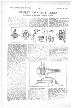
The most interesting patent with which we have to deal this week .is undoubtedly N. 133,191, by F. G. Woollard, and E. G. Wrigley and Co., Ltd. It is concerned with Lack axle design, and its principal aim is that of improving the accessebility of the driving and differential gears. It has every appearance of having attained the object of the inventors, and marks a step forward in rear axle design. There have, of course, been previous constructions in which it has been possible, after withdrawing the driving shafts, to take out the worm, worm wheel, and differential gear, and in bevel-driven axles it has been possible to withdraw the differential gears and main bevel wheel without any appreciable disturbance of the rest of the axle, but the present invention allows of the whole of the driving gear, main bevel and bevel pinion included, complete with its casing and framework, without even disturbing the alignment of the main driving bevels or the depth to which they are engaged.
The driving gear is not, as is customary, carried from the axle case .proper, but is entirely supported by a. separate framework, which is deeply epigoted in a forwardly projecting extension of the axle case. It is further supported by two pairs of substantial bolts, whieh are ingeniously made to perform a triple duty. II reference be made to our illustration, which is reproduced from the patent specification, it will be noticed that the rear end of the propeller shaft is splined and projects half-way through a plain muff coupling. It is further secured to the coupling by means of a pin which is driven through both and then riveted over. The forward end of the shaft which carries the main bevel pinion is also splined to fit the same coupling into which it enters, but to which it is not secured by any pin or other permanent fastening. The bevel pinion shaft is supported on roller bearInge which are carried in a short sleeve or cuff, which itself screws into the forward end of the casting which carries the whole of the gearing, and which, at this end, spigots into the forward extension 4:d the axle ease. The same casting extends backwards and supports the roller bearings for the differential gear and the crown bevel in the usual fashion. The supports for the main realer bearings are in halves, as usual, and the cap bolts for them are the bolts to which reference has been made already as performing a triple function. The bosses_ on the gear frame or casting, on the for
B56
ward side, are extended so as almost to meet the inside of the axle case itself, and on the latter are formed corresponding bosses. The bolts are each formed with a collar so that they can be firmly secured at the axle case. The bosses on the gear frame rest on the collars, the other halves of the roller bearing supports are put in place and secured in the usual manner by nuts on these muchused bolts, whose service is not yet completely told. They are extended till further, though somewhat reduced in diameter' and servo as the sole means of securing the rear cover of the axle case, which cover closes a hole sufficiently large to permit of the removal, through it, of all the framework, gears, etc. The arrangement is such, as will be apparent., that, were such a proceeding necessary, or even, perhaps, advisable, it would be possible, by removing first the forward nuts on the holding together bolts, to remove the gearing at the same tune as the cover, instead of after it.
Other Patents of Interest.
A peculiar defect of aluminium as a material for gear and crank eases is its liability to give way if a stud is screwed into it. Bolts, however, are frequently inconvenient, mainly because of the difficulty of holding them while the nuts are being screwed on, and also because of the risk of their dropping into the interior of the gear or crank case. In specification No. 133,093 G. E. Bradshaw and A.B.C. Motors, Ltd., describe a construction which is intended to obviate these troubles.
A simple valve timing indicator, particularly adaptable for rotary engines, is described in specification No. 133,151, the patentee being S. C. Martin. The brake gear which Mr. F. W. Lanchester has patented in No. 133,156 embodies a number of rings like piston rings, which are successively expanded against the interior of the brake drum. It is equally effective in either direction.
In No. 133,158 we have another device for manipulating the needle valve of the Holley carburetter. The 'patentee is C. E. Thorne.
No. 133,175, by G. Buchet and A. Simpers, also concerns carburetter construction. The jet is shrouded by a chamber in the forns of an inverted cone, the exterior of which, according to its position, regulates the suction on the jet. The conical part is lifted or lowered by the carburetter control lever In the gearbox described in No. 133,251 the gears throw the oil into troughs in the upper part of the box, whence it drains back into a filter and thence to the gears again. The patentee is F. B. Shaw.
The improved differential or compensating gear, which is the subject of No. 133,278, by J. D. Allen, appears to consist of a double pair of ratchet free wheels in the middle of an ordinary differential case.