


• Holding
Page 51
Page 52
Page 53
If you've noticed an error in this article please click here to report it so we can fix it.
back
the load
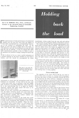
rHE rapid increase in brake performance of commercial vehicles over the past few years does not appear to have been accompanied by a corresponding improveent in the method of restraining the load. In the ajority of cases the load is simply laid in the body, or 1 the platform, and only the headboard prevents the load tting the cab on braking. It may be argued that while hide manufacturers provide a tray in which to put a ad, operators are justified in simply resting the load in the iy.
If this is always to be so, a more careful estimation of e stresses imposed on the body members by the load is :cessary, and this should be accompanied by stress :asurements to ensure that the assumptions made in the lculations are reasonable. It may well be the case, and s article goes some way to proving it, that the weight natty involved in providing sufficiently robust ends and les to the load-carrying tray is so great on modern mmercial vehicles that other means will have to be ,ind to keep the load in place.
Whilst we are only concerned with headboards in this the higher cornering speeds now used mean that e panels may have to be strengthened_ Furthermore, the her acceleration possible with modern vehicles will pose more load on the tailboard.
Before making an estimation of the loads that could tsonably be applied to a truck headboard under braking, is worth while considering what happens to the vehicle d its load as the brakes are applied. When the brake dal is pushed with a given force it is well known that proportional deceleration of the vehicle is produced. is is commonly measured with a deceleration meter. It also well known that braking produces a weight
transference, taking weight from the rear axle and adding it to the front axle, giving the vehicle a front-down attitude.
The vehicle pitching will start quickly and gradually slow down until a constant angle is reached. The load is moving with the vehicle before the brakes are applied and it only imposes a load equal to its weight on the floor of the truck. When the vehicle starts to pitch the truck floor at the rear is accelerated upwards and the force imposed by the load on the floor is increased, although this increase is only temporary because there will be no vertical movement of the floor when the constant pitch angle is reached and the load will again impose a force equal to its weight on the floor.
Just before this steady state is reached we have the load moving upward while the floor is slowing down its upward movement to reach the steady pitch angle. The inertia of the load will now carry it up away from the floor and thus decrease the force between the load and the floor. The friction between the load at the rear of the vehicle and the floor is reduced from its normal value at a time when the full braking force is being applied.
Forces on the Load
The opposite of this force will be felt by any load in front of the centre of pitch, i.e., friction will be increased, but since the centre of pitch is normally towards the front of the load the net effect will be a reduction in friction. Since the load imposes a forward force on the vehicle equal to its weight times the decelerometcr reading, and since this force can be resisted only by the headboard and the friction on the floor, the temporary reduction of the friction force makes the headboard load greater.
No measurements have been made of the friction force between the load and the truck floor while braking, and in order to design truck bodies correctly such measurements will have to be taken. It is, therefore, necessary to make an assumption, and to be safe we will assume that the headboard takes almost the full inertia force of the actual load in tons multiplied by the decelerometer reading expressed as a fraction of the force of gravity :-where W = load in tons and G = decelerometer reading in percentage of gravity. It should be noted that the decelerometer reading includes the effect of vehicle tilt and is thus the correct value to be used when calculating headboard loads.
Now decelerometer readings up to 90 per cent, gravity have been recorded on heavy vehicles, and on light van
readings of over 100 per cent, are not unknown. If the effect of load-to-floor friction is ignored this means that the headboard may have to stand a total force equal to the weight of the load distributed over its area We will consider three types of vehicle; a normal dropside truck or platform vehicle, where the headboard is only secured along its bottom edge; a boxvan, where the front end of the box is fixed in a rigid frame; and a tipper, where the headboard is rigidly held at the sides and where the load is of a special type. The headboard on a drop-side or platform body normally has two upright stanchions which carry the load to the underbody structure.
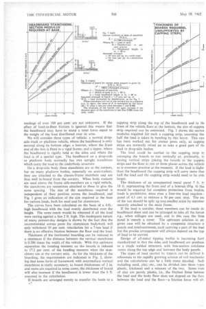
On a drop-side body these stanchions are at the corners, but on many platform bodies, especially on semi-trailers, they are attached to the chassis-frame members and are thus well in-board from the corners. When body runners are used above the frame side-members on a rigid vehicle, the stanchions are sometimes attached to these to give the same spacing. The size of the stanchions required is independent of their position across the headboard, and Fig. 1 gives an indication of the size required at the base for various loads, both for steel and for aluminium.
The curves have been calculated on the basis of a 4-ft.high headboard with the load evenly distributed over the height. The same result would be obtained if all the load were resting against a line 2 ft. high. The inadequate nature of many present-day designs is shown by the fact that the recommended corner posts for aluminium bodywork will only withstand 10 per cent, retardation for a 7-ton load if there is no effective friction between the floor and the load.
Thickness of the horizontal boarding can be reduced to a minimum if the distance between the vertical stanchions is 0.586 times the width of the vehicle. With this optimum separation the bending moment on the boards is reduced to 17.2 per cent. of the bending moment when the stanchions are at the corners only. As for the thickness of the boarding, the requirements are indicated in Fig. 2, showing that some form of framework with intermediate vertical stanchions is really necessary, as board thicknesses of 2 in. and more are required in some cases; the thickness of board will also increase if the headboard is lower than the 4 ft. assumed in the calculation.
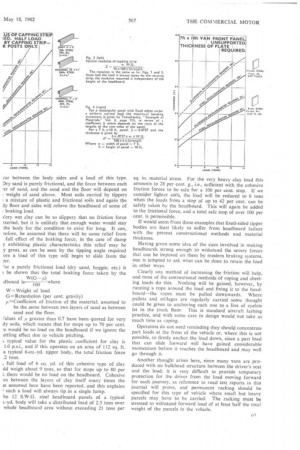
If boards are arranged merely to transfer the loads to a p' capping strip along the top of the headboard and to thi front of the vehicle floor at the bottom, the size of cappini strip required can be estimated. Fig. 3 shows the sectiot modulus required for such a capping strip, assuming tha half the load is taken in bending by this beam. This casi has been worked out for corner posts only, as cappirn strips are normally relied on to take a good part of th+ load in drop-side bodies.
The load could be carried to the capping strip LI: arranging the boards to run vertically or, preferably, b: having vertical strips joining the boards to the cappim strips and the floor at two or three places across the vehicle as is common practice at the moment. If the load is highe than the headboard the capping strip will carry more thai half the load and the capping strip would need to be evei larger.
The thickness of an unsupported metal panel 7 ft. b] 10 ft. representing the front end of a boxvan (Fig. 4) tha would be required for complete protection from brakin; loads is prohibitive, since even a four-ton load requires panel of 4.5 cwt. to restrain a 50 per cent. stop. The em of the van should be split up into smaller areas by member securely attached to the main frame.
If the load is suitable, these members can be inside tit headboard sheet and can be arranged to take all the forceE e.g., when stillages are used, and in this case the fron panel is merely a cover. The optimum solution in an given case will be obtained by a composite structure o panels and reinforcements, each carrying a part of the load but the precise arrangement will always depend on the typ of load to be carried.
Design of all-metal tipping bodies is becoming fairl standardized in that the sides and headboard are produce+ as a single welded structure, with box-section reinforce ments along the top edge and between the body panels.
The types of load carried by tippers can be defined b references to the rapidly growing science of soil mechanics and the calculations can be a little more detailed. Soil) including sand, clay, etc., can be divided into three types plastic, frictional and a mixture of the two. Some tvne of clay are purely plastic, i.e., the friction force hetwee the load and the body floor does not depend on the fore between the load and the floor--a friction force will ais zur between the body sides and a load of this type. Dry sand is purely frictional, and the force between each vr of sand, and the sand and the floor will depend on weight of sand above, Most soils carried by tippers a mixture of plastic and frictional soils and again the ly floor and sides will relieve the headboard of some of braking load.
Jery wet clay can be so slippery that no friction force xerted, but it is unlikely that enough water would stay the body for the condition to exist for long. It can, refore, be assumed that there will be some relief from full effect of the braking force; in the case of damp y exhibiting plastic characteristics this relief may be y great, as can be seen by the tipping angle required 'ore a load of this type will begin to slide from the or a purely frictional load (dry sand, hoggin, etc.) it be shown that the total braking force taken by the dboard is100 where W=Weight of load
G----Retardation (per cent, gravity)
ti=Coefficient of friction of the material; assumed to be the same between two layers of sand as between sand and the floor.
Talues of t greater than 0.7 have been quoted for very dy soils, which means that for stops up to 70 per cent. would be no load on the headboard if we ignore the ettling effect due to vehicle pitching.
typical value for the plastic coefficient for clay is 1.0 p.s.i., and if this operates on an area of 112 sq. ft. a typical 6-cu.-yd. tipper body, the total friction force .2 tons.
full load of 6 cu. yd. of this cohesive type of clay ild weigh about 9 tons, so that for stops up to 80 per 1. there would be no load on the headboard. Cohesive vs between the layers of clay itself many times the se assumed here have been reported, and this explains such a load will always tip in a single lump. he 12 S.W.G. steel headboard panels of a typical 1.-yd. body will take a distributed load of 2.5 tons over whole headboard area without exceeding 21 tons per
sq. in. material stress. For the very heavy clay load this amounts to 28 per cent. g., i.e., sufficient with the cohesive friction forces to be safe for a 100 per cent. stop. If we consider lighter soils, the load will be reduced to 6 tons when the loads from a stop of up to 42 per cent, can be safely taken by the headboard. This will again be added to the frictional force, and a total safe stop of over 100 per cent, is permissible.
If would seem from these examples that fixed-sided tipper bodies are least likely to suffer from headboard failure with the present constructional methods and material thickness.
Having given some idea of the sizes involved in making headboards strong enough to withstand the severe forces that can be imposed on them by modern braking systems, one is tempted to ask what can be done to retain the load in other ways.
Clearly any method of increasing the friction will help, and most of the conventional methods of roping and sheeting loads do this. Nothing will be gained, however, by running a rope around the load and fixing it to the headboard—the ropes must be pulled downwards. Where pallets and stillages are regularly carried some thought could be given to anchoring each one to a line of eyelets let in the truck floor. This is standard aircraft lashing practice, and with some care in design would not take as much time as toping.
Operators do not need reminding they should concentrate part loads at the front of the vehicle or, where this is not possible, to firmly anchor the load down, since a part load that can slide forward will have gained considerable momentum before it reaches the headboard and may well go through it.
Another thought arises here, since many vans are produced with no bulkhead structure between the driver's seat and the load; it is very difficult to provide temporary protection for the driver from the load moving forward for each journey, as reference to road test reports in this journal will prove, and permanent racking should be specified for this type of vehicle where small but heavy parcels may have to be carried. The racking must be stressed to withstand forward load of at least half the total weight of the parcels in the vehicle.