


Rubber Suspension for Trailers
Page 72
If you've noticed an error in this article please click here to report it so we can fix it.
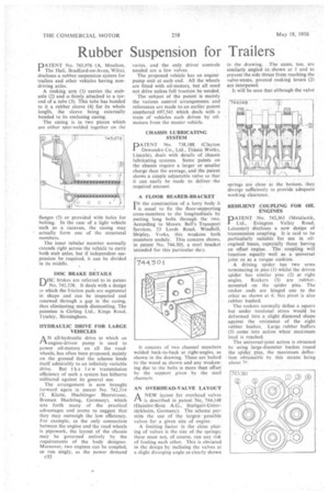
PATENT No. 743,976 (A. Moulton, The Hall, Bradford-on-Avon, Wilts), discloses a rubber suspension system for trailers and other vehicles having nondriving axles.
A rocking arm (1) carries the stubaxle (2) and is firmly attached to a tyeend of a tube (3). This tube has bonded to it a rubber sleeve (4) for its whole length, the sleeve being externally bonded to its enclosing casing.
The casing is in two pieces which are either spot-welded together on the flanges (5) or provided with holes tor bolting. In the case of a light vehicle such as a caravan, the casing may actually form one of the structural members.
The inner tubulari member normally extends right across the vehicle to carry both stub axles, but if independent suspension be required, it can be divided in its middle,
DISC BRAKE DETAILS roc brakes are referred to in patent LI No. 742,338. It deals with a design in which the friction pads are segmental in shape and can be inspected and renewed through a gap in the casing, thus eliminating much dismantling. The patentee is Girling Ltd., Kings Road, Tyscley, Birmingham.
HYDRAULIC DRIVE FOR LARGE VEHICLES
AN all-hydraulic drive in which an engine-driven pump is used to power oil-motors on all the roadwheels, has often been proposed, mainly on the ground that the scheme lends itself admirably to an infinitely variable
drive. But the 1 o w transmission efficiency of such a system has hitherto militated against its general use. .
The arrangement is now brought forward again in patent No. 742,314• (T. Klatte, Huchtinger Heerstrasse, Bremen Hnehting, Germany), which sets forth many of the practical advantages and seems to suggest that they may outweigh the low efficiency. For example, as the only connection between the engine and the road wheels is pipework, the layout of the chassis may be governed entirely by the requirements of the body designer. Moreover, two engines can be coupled, or run singly, as the power demand
c32 varies, and the only driver controls needed are a few valVes.
The proposed vehicle has an enginepump unit at each end. All the wheels are fitted with oil-motors, but all need not drive unless full traction he needed.
The subject of the patent is mainly the various control arrangements and references are made to an earlier patent numbered 697,541 which deals with a train of vehicles each driven by oilmotors from the master vehicle.
CHASSIS LUBRICATING SYSTEM
PATENT No. 738,188. (Clayton Dewandre Co., Ltd., Titanic Works, Lincoln), deals with details of chassis lubricating systems. Some points on the chassis require a larger or smaller charge than the average, and the patent shows a simple adjustable valve so that it can easily be made to deliver the required amount.
A FLOOR BEARER-BRACKET
IN the construction of a lorry body it I is usual to fix the floor-supporting cross-members to the longitudinals by
• putting• long bolts through the two. According' to Messrs. Bell's Transport Services, 23 Leeds Road. Windhill, Shipley, Yorks, this weakens both members unduly. This concern shows, in patent No. 744,301, a steel bracket intended for this particular duiy.
It consists of two channel members welded back-to-back at right-angles, as shown in the drawing. These are bolted to the wood as shown and any weakening due to the bolts is more than offset by the support given by the steel channels.
AN OVERHEAD-VALVE LAYOUT
ANEW layout for overhead valves is described in patent No. 744.148 (Daimler-Benz A.G., Stuttgart-Unterttirkheim, Germany). The scheme permits the use of the largest possible valves for a given size of engine.
A limiting factor in the close placing of vahes is the size of the springs; these must not, of course, run any risk of fouling each other. This is obviated in the design by inclining the valves at a slight diverging angle as clearly shown in the drawing. The cams, too, are similarly angled as shown at 1 and to prevent the side thrust from reaching the valve-stems, pivoted rocking levers (2) are interposed.
It will be seen that although the valve springs are close at the bottom, they diverge sufficiently to provide adequate work ing clearance.
RESILIENT COUPLING FOR OIL ENGINES
DATENT No. 743,361 (Metalastik,
Ltd., Evington Valley Road, Leicester) discloses a new design of transmission coupling. It is said to be particularly suitable for use in oilengined buses, especially those having an offset engine. The coupling will function equally well as a universal joint or as a torque cushion.
A driving spider has two arms terminating in pins (I) whilst the driven spider has similar pins (2) at right angles. Rockers (3) are rubbermounted on the spider pins. The rocker ends are hinged one to the other as shown at 4: this pivot is also rubber bushed.
The rockers normally define a square but under torsional stress would be deformed into a slight diamond shape against the resistance of the eight rubber bushes. Large rubber buffers (5) come into action when maximum load is reached.
The universal-joint action is obtained by using large-diameter bushes round the spider pins, the maximum deflection obtainable by this means being about 70.