


Brake Refinement for Steerable Wheels
Page 32
If you've noticed an error in this article please click here to report it so we can fix it.
A Resume of Recently Published Patent Specifications TO provide a brake mechanism. suitable for receiving its actuating pull at an angle is the object of a design shown in patent No. 519,389 by Automotive Products Co., Ltd., and G. Gates, both of Brock House, Longhorn Street, London, W.I.
The drawing shows this concern:s well-known operating scheme, in which shoe-engaging plungers (4) are spread by rolling sectors (5) being pulled to the right by a rod (3). The improvement consists of the use of a swinging link (2), pivoting on a pin (I) located in a rearward direction.
By this means; the angularity of the pull-rod when steering does not stress the brake mechanism, whilst the geometry of the scheme shows that it gives a slight " Ackerman " effect, resulting in an increased braking effort on the inner wheel of the turning circle FUEL-LIFT PUMP WITH CAM RETURN ACTION
AN improved form of pump for lifting fuel from the tank to the carburetter or injection pump is shown in patent No. 518,594 by S.P.I.C.A., 37, Via Bartolomeo, Bosco, Italy.
An engine-driven cam (3) oscillates a tappet which transmits its motion to the spring-loaded piston (6) via a central rod. When the piston moves to the right, fuel is drawn into the space (5). On the leftward stroke, the fuel is forced through bores (4) in the piston, past a spring-loaded valve (1), and reaches the space (2) leading to the delivery. The latter space is always maintained under pressure from the piston spring and, being usually kept full, the tappet stroke consists principally of lost motion. The patent also describes a pedal-operated priming device for use when starting.
INJECTION-PUMP LINE-PRESSURE UNLOADING VALVE Tprevent dribble at the nozzle is the object of a device shown in patent No 519,091 by Limited Company, Prague, Czechoslovakia. The drawing shows the upper end of ,an injection pump, the delivery valve
being represented by a spring-loaded ball (3). The pressure-relieving device consists of a small spring-loaded piston-valve (2) whose cylinder is restricted as to fuel flow by a smallbore nipple (1).
On the delivery stroke, the piston (2) lifts against its spring until injection pressure is reached, after which the charge passes the ball valve. On the return stroke, after the ball valve has closed, the piston descends and reduces the volume of the piping, thus reducing the pressure. The object of the nipple (I) is to throttle the action of the piston at high speeds, during which, it is stated, the need for pressure unloading is reduced. TWO COMPLETE SYSTEMS FOR HIGH-EFFICIENCY ENGINES
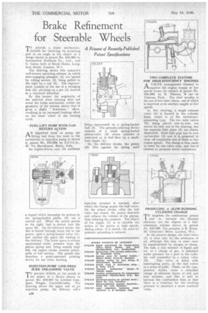
AVALVE arrangement claimed to improve the engine torque at low speeds forms the subject of patent No. 518,856, by R. Pescara, 6 rue de Teheran, Paris. The chief novelty is the use of two inlet valves, one of which is deprived of its mixture supply at low speeds.
In the drawing, a single exhaust valve (4) is located in the cylinder bead, which is of the turbulencepromoting type. The two inlet valves (3), being placed side-by-side, are shown by only one in the drawing, but the separate inlet pipes (2) are clearly illustrated. Each inlet pipe has its own carburetter (1) and it is proposed to close off completely one of these at low engine speeds. The charge is thus made to enter by one valve only, and this is claimed to promote better turbulence.
PRODUCING A SLOW-BURNING CYLINDER CHARGE
TO lengthen the combustion period and to increase the thermal efficiency are the objects of a fueladmission scheme shown in patent No, 519,026. The patentee is R. Erren, 26, Gloucester Mews, London, W.I.
In the present design, the inlet valve (1) is used only for the admission of air, although this may in some cases be supplemented by oxygen or steam. The fuel, a rich mixture of liquid and air, or a charge of gas, is admitted under pressure via a port in the cylinder wail controlled by a rotary valve (2). This valve is fitted with interrupting ports, so the fuel enters in a series of puffs. These, on the compression stroke, cause a stratified charge of alternate layers of rich and lean mixture, and this is said to increase the combustion time so that there is a tendency for the working pressure to maintain a more constant value.