


A, ONE-WAY MOTOR PLOUGH.
Page 28
If you've noticed an error in this article please click here to report it so we can fix it.
A Résumé of Recently Publithed Pater:is.
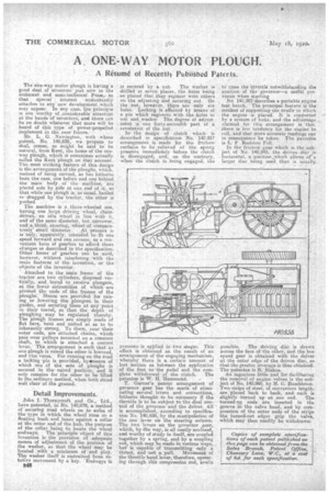
The one-way motor plough is having a good deal. of attention just now in the teehnical and semitechnical Press,so that special : interest_ undoubtedly attaches to any new development which may appear. In any case, the princip!e is one worthy of ,considerable attention at the hands of inventors; and there can he no doubt -whatever that more will be heard of this 'type of .power-propelled implement in the near future.• Mr. L. G. Newington, with whose patent, No, 140,858, we propose to deal; 'comes:, as might be said to be natural, from Kent, the home of the one-way plough, which is sometimes actually called the Kent plough on that account. The most striking feature of this design is the arrangement of the ploughs, which, instead of being carried, as has hitherto been thacase, one before and one behind tilemain body . of themathine; are placed side by side at one end of it, so that while one plough is, as-usual, hauled or dragged by the tractor, the other is
pushed. -
The machine is is three-wheeled one, having one large driving wheel, chain. driven, an idle wheel in line with it, and of the same diameter, but narrower, ander third, steering, -wheel, of conipara tively. Small diameter. At present
is Only; apparently; intended to fit one speed forward and one reverse, as a convenient form of gearbox to afford those changes as described in the specification. Other _forms of gearbox can be used, however; without interfering with the main features of the invention, or the objects of the inventor. •
Attached to the main frame of the tractor are two cylinders, disposed vertically, and bored to receive plungers, at the lower extremities of which are pivoted the ends of the frames of the ploughs. Means are provided for raising or lowering the plungers in their guides, and securing them at any 'point in their travel, so that the depth of ploughing may be regulated thereby. The .plongh frames are simply made of flat bars, bent and united so as to be inherently strong. To them, near their outer ends, are attached chains, which pass over pulleys mounted on a common shaft, to which is attached a control lever. The arrangement is such that as one plough is raised the other is lowered, and vice versa. For running on the road a locking -pin is provided, byemeans of which one of the sets of plough.s is secured in the raised position, and it only remains for the other to be lifted in the ordinary method, when both sand well clear of the ground.
Detail Improvements.
John I. Thornyeroft and Co., Ltd., have patented, in. No. 140,879, a method of securing road wheels on to axles of the type in which the wheel rune on a floating bush and bears against a cellar at the outer end of the hub, the purpase of the collar • being to locate the wheel endwayS. The 'principle object of this invention is the provision of adequate means of adjustment of the position of the washer, so .that the wheel may be located with a minimum of 'end play. The washer itself is restrained from rotative movement by a key. Endways it is secured by a nut. The washer is drilled in seven places, the holes being so placed that they register with others on the adjusting and securing nut. On the nut, however, there are only six holes. Locking is effected by means of a pin which registers with the holes in nut and washer The degree of adjustinnt is one forty-secondth part of a revolution of the nut.
In the design of clutch which is described in specification No. 140,957 arrangement is made for the friction surfaces to be relieved of the spring pressure immediately before the clutch is disengaged, and, on the contrary, when the clutch is being engaged, the pressure is applied in two stages. This effect is obtained as the result of an arrangement of the engaging mechanism, whereby there is a certain amount of lost motion as between the application of the foot to the pedal and the com
plete withdrawal of the clutch. The patentee is W. H. Hammond.
T. Garner's patent arrangement of governor gear has the merit of eliminating several levers and connections, hitherto thought to be necessary if the throttle is to be subject to the dual control of the .governor and the driver. All is accomplished, according to specification No. 140,958, by the manipulation of the one lever on the steering column. The two levers on the governor gear, which, by the way, is all neatly enclosed, and worthy of study in iteelf, are coupled together by a spring, and by a coupling rod, which may be made in various ways, but' is capable of transmitting only a thrust, and not a pull. Movement of the throttle hand lever, therefore, operating through this compression rod, avails
to close the throttle notwithstanding the position of the governor—a useful provision when starting
1No 140,902 describes a portable engine test bench. The principal feature is the method of supporting the cradle in which the engine is placed. It is supported by a system of links, and the advantage claimed for this arrangement is that there is lets tendency for the engine to roll, and that more accurate readings can in 'consequence be taken. The patentee is L F Itudsten Fell.
In the friction gear which is the .subject of No. 140,945, the driven, disc is
horizontal, a position allows' or a larger disc being used than is usually possible. The driving disc is drawn
across the face of the other, and the low, speed gear is obtained with the driver at the outer edge of the driven disc, so that the greater leverage is thus obtained. The patentee is R. Blakoe.
An ingenious little tool for facilitating the removal of engine valves is the subject of No. 140,960, by H. C. Hambleton. Two strips of steel, of convenient length, are placed back to back, and each is slightly turned up at one end. The turned-up ends are inserted in the groove in the valve head, and by compression of the outer ends of the strips the turned-out edges grip the valve, which may then readily be withdrawn: