


From Engine to Axle.
Page 14
Page 15
If you've noticed an error in this article please click here to report it so we can fix it.
Following the recent papers read before the Institution of Automobile Engineers, which have dealt respectively with rear axles and engines, a third has now been read, dealingwith those parts of the transmission which were not included in the previous two reviews. Major Shilson, the author, disclaims any intention to "present any new features or enunciate any new theories," but he has dealt with his subject in an informative manner, and we therefore reproduce the paper in instalments as opportunity occurs. The present instalment follows that on page 218 last.
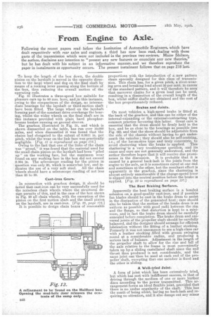
'To keep the length of the box down, the double pinion on the layshaft is moved in the opposite direction to the large wheel and dog on. the final shaft by means of a rocking lever passing along the bottom of the ,box, thus reducing the overall motion of the operating rods. Fig. 31 illustrates a th!ree-speed box suitable for pleasure cars up to 80 mm. bore, and,in this instance, owing to the compactness of the design, no intermediate bearings for the layshaft or third-motion shaft have been fitted. The large wheel on the layshaft forming part of the constant drive overhangs the bearing, whilst the wider wheels on the final shaft are in this instance provided with plain hard phosphor:bronze bushes running on ground sleeves. • The gearbox illustrated in Fig. 31, and which is shown dismantled on the table, has run over 10,000 miles, and when dismantled it was found that the chains had elongated to the extent of 0.0011 in. per pitch, whilst the wear on the link face was practically negligible. [Fig, 31 is reproduced on page 1781 Owing to the fact that one of the links of the chain was "proud," it was found that the material used for the small chain pinion on the layshaft had been "piled up" on the working face, but the, maximum wear found on. any working face in the box did not exceed 0.004 in. The scleroscope reading for the pinion in 'question was only 20, which is somewhat low, and indicates the use of a very soft steel. All the chain • . Wheels should have a scleroscope reading of not less than 25 to 30.
Cast-iron Gears.
In connection with gearbox design, it should be noted that cast-iron can be very successfully used for the noiseless chain wheels where the structural design permits of this, and in the case of the box shown in Fig. 29 all chain wheels, with the exception of the pinion on the first motion shaft and the small pinion on the layshaft, are in cast-iron. [Pig. 29, page 178.j
It is possible to design chain boxes of reasonable
proportions with the introduction of a new pattern chain specially designed for this class of transmission. This chain has, for a given pitch, a rivet-wearing area and breaking load about 50 per cent, in excess' of the standard pattern and it will therefore be seen' that narrower chains for a given load can be used,. resulting in a diminution of the overall length of the box, whilst stiffer shafts are obtained and the cost of the box proportionately reduced.
Brakes and Joints,
On most vehicles a high-speed brake is fitted at the back of the gearbox, and this can be either of the internal-expanding or the external-contracting type, common practice favouring this latter. Great care is essential that the drum should be firmly held in the box, and be as close to the bearings as possible (see Fig. :32), and that the shoes should be adjustable from the side of the chassis without having to get underneath the vehicles ; they should also be self-centring, i.e., of the locomotive type and truly concentric, to avoid chattering when the brake is applied. This chatterinvis a very troublesome question, and its cause and .cure are not generally understood, and the author therefore hopes that it will receive due prominence in the discussion. It is probable that it is caused by a general back-lash in the joints from the engine to the axle, as it is sometimes cured at one end and sometimes at the other, but the resultant effect is apparently in the gearbox, since the chattering is almost entirely unnoticeable if the change-speed lever is slipped into the neutral position before the brake is applied. [Fig. 32 is reproduced on page 197.] The Best Braking Surfaces.
Apparently the best braking surface is a bonded asbestos on, a good-quality cast-iron, and if possible fan blades should be cast in the brake drum to assist in the dissipation of the generated heat ; care should also be taken that the section of the brake drum is as uniform as possible with good radii between the rim and the flange, so that distortion is kept to a minimum, and-in fact the brake drum should be carefully annealed before completion. The brake drum and universal joints of the propeller shaft should be carefully balanced, fnd the designer should arrange for efficient lubrication without the fitting of a leather stocking. Formerly it was not uncommon to see a high-class car with a, leather stocking _filled with grease swinging round at a considerable radius, and producing a serious lack of balance. Adjustment in the length of the propeller shaft to allow for the rise and fall of the axle relative to the frame is most conveniently taken up by a sliding castellated shaft since the end thrust thus produced is not considerable, and the same joint canthen be used at each end of the propeller shaft, -excepting that one member is fixed and the other is sliding.
A Well-tried Joint,
A form of joint which has been extensively tried, but which has met with indifferent success, is that of driving through the medium of one or more leather discs according to the power transmitted. This arrangement forms an ideal flexible joint, provided that there is no undue angularity ofthe shaft. This has the merit of being silent, having no back-lash and requiring no attention, and it also damps out any minor vibrations, but the stress imposed is liable to tear the joint unless it is well supported and secured without any sharp edges on the fork or metal washers. The quality of the leather is of great importance, and it must be of a tough and oily nature. When more than the one disc is used some firms stitch them together, and some separate them by means of steel washers ; the latter method Would appear preferable, since three or lour discs stitched together make a very stiff piece and rob itoof its ability to take up angular variations. For light car work there would appear to bonothing against its adoption, and its low cost of manufacture is an additional attraction. Whilst it is satisfactory for town work, for propeller shaft joints on commercial vehicles, experience goes to show that under extreme conditions of service, the joint is , incapable of standing up to its work, but the author is • of the opinion that this is due to insufficient knowledge of its design, and to unsuitable conditions of employment. Such a joint requires frequent inspection, so that any trouble may be at once observed, and the fact that it is running quite successfully on omnibuses shows that it is capable of coping with ordinary conditions of service.
The universal joints, owing to their position on the chassis, are always liable to neglect, and great care should therefore be taken in their lubrication. The author has found that fot a good specific pressure on the pin, say, 1000 lb. per sq. in., it is preferable to obtain the requisite area in length rasher than in diameter of the pin owing to the fact that the wear is directly proportionate to the diameter. In the case of the forked type of joint it is usual to fix the bush in the driving ring or box, but the author is inclined to think that a floating bush, so that it can rotate either on the pin or in the ring, is a more satisfactory arrangement, care being taken that both surfaces are properly lubricated.
The Best Universal Joint.
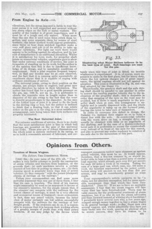
For extreme conditions of service, there is no doubt that the most satisfactory joint is that in which ball bearings are mounted on the pins of the universal joint forks. These pins are of robust dimensions and the whole joint is entirely enclosed in its casing, so as to hold a reasonable amount of lubricant, and cer tainly when this type of joint is fitted, no trouble whatsoever is experienced. It is, of course, more expensive to make in the first place, but for heavy duty, • where the low upkeep charges are of great importance, the initial expense should not tell against its adoption. This joint is illustrated in Fig. 33, and was first adopted by the Deasy Co.
Theoretically, the gearbox shaft and the axle driving shaft should be parallel to one another in order to correct the varying angular velocity due to the inclination of the propeller shaft ; this is desirable in order that scraping of the tyre on the road may be avoided, but if there is much angularity to the propeller shaft when at rest, this arrangement is unsightly and is usually dispensed with, and the whole of the angularity is takep up on the forward' joint, leaving the tyres to take 'care of themselves.
In order to overcome this defect in design, the DaSraler Co. inclined their engine so as to form a direct line with the axle. In .commercial vehicles with the worm drive on top, a straight drive can usually be obtained with little or no angularity of the shafting, and in the case of a double-reduction bevel axle it is preferable to mount the countershaft over, instead of in front of, the axle for this reason, and also to prevent any undue tendency to rotation of the axle due to the momentum of this part.