


Patents Completed.
Page 26
If you've noticed an error in this article please click here to report it so we can fix it.
Complete specifications of the following patents will be sent to any address in the United Kingdom upon receipt of eightpence per copy at the Sale Branch, Patent Oifice, Holborn, W.C.
SLEEVEVALVE ENGINE.—Knight. —No. 9,280, dated 16th April, 1910.— This invention relates to engines of the type in which a sleeve forms the actual cylinder in which the piston works and is surrounded by a sliding-aleeve valve
situated in the cylinder casing. The invention consists in providing the reciprocating cylinder with a fixed guide so as to relieve the slide valve from any strain or pressure due to the lateral thrust of the piston on the working stroke. A further feature of the invention is forming the cylinder casing with a varying radius at different portions of its circumference and arranging the slide valve in that part of the casing which has the larger radius. The slide valve is placed on the side of the engine which is not subjected to lateral thrust during the working stroke, and the valve movements are, therefore, considerably eased. The slide valve and inner sleeve are reciprocated by suitable eccentrics or cranks chain-driven from the engine
shaft. The inlet port is arrangedto enter near the top of the combustion chamber around the sparking plug, so that the explosion is not weakened by having, as is customary, a mixture of the exhaust and new gases around the sparking plug.
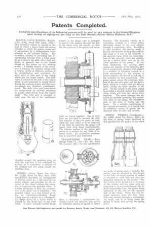
WHEEL.—Albion Motor Car Co.— No. 11,522, dated 7th May, 1910.—This specification describes an arrangement of driving wheel fur a side-chain-driven motor vehicle, and provides for the removal of the wheel without the necessity of removing the sprocket wheel. A further advantage is that the construction of the chain case is simplified. The sprocket wheel, or a ring formed on it, has an outwardly-extending flange which acts as a spigot for a corresponding flange acting as a faucet which is formed on the metal hub of the road wheel. A small inwardly-turned flange formed on the spigot part is arranged to receive bolts passing through the hub of the wheel from the outside, so that the two portions of the spigot and faucet joint are bolted together. One or more keys are provided to prevent the relative rotation of the two parts, so that, when the road wheel is to be removed, if the bolts be removed, the spigot and faucet joint slide apart longitudinally. The interior surface of the spigot part serves as a surface for any form of internal brake. An alternative construction ia described and illustrated.
CHANGE-SPEED GEAR. —Rothplunge Pump Co., Ltd.—No. 487, dated 7th January, 1911.—In this specification there is described a combination hydraulic clutch and epicyclic gear giving an indefinite number of speeds in either direction. The hydraulic clutch, as is customary, consists of a rotary pump delivering liquid to its own suction through a regulating valve. According to this invention the driving shaft is fixed to one member of the pump and has also fixed to it one of the elements of the epicyclic train, while the other members of the epicyclic train are carried, one by a driven shaft, and one by the other member of the pump. In the form illustrated, the driving shaft carries one member of the epicyclic gear and is eccentrically situated with respect to a number of cylinders formed in a block surrounding it, the pistons, in known manner, are moved in and out of the cylinders by this eccentricity. The pump casing carries the planetary members of the epicyclic gear, and the driven shaft, which is co-axial with the driving shaft, carries the third member of the gear. On the outside of the pump casing is provided a suitable surface for a brake strap which will lock this casing when required. The speed changes are obtained by suitably operating the controlling valve in the pump, the alternative gear in the train of wheels and the brake. By a suitable combination of the various movements, it is stated that an indefinite variety of speeds can be obtained both forward and reverse.
SPRING WHEELS.—Horstmann.— No. 5,609, dated 7th March, 1910.—In the form of spring wheel described in this specification the spokes of the wheel are made of spring steel of suitable flat section, and are attached to two flanges on the hub ; an equal number of spokes is attached to each hub and they are staggered relatively to one another. The flat section of the spokes lies in the plane of the wheels, and the outer ends are connected to an inverted-channel rim by short inextensible links, the spokes being connected to the rim on the opposite side of the wheel. When the rim becomes eccentric from the hub, these links are rotated through a corresponding angle, and in so doing cause the spokes to bend, thus giving the spring action.