


T he first generation of electronically controlled trucks had multiple electronic
Page 110
If you've noticed an error in this article please click here to report it so we can fix it.
control units (ECUs) controlling various functions such as engine management and anti-lock braking.
They all worked largely in isolation and frequently provided duplicated information. For example, there might have been as many as five coolant temperature sensors, all working for different systems and each with its own bit of wiring loom.
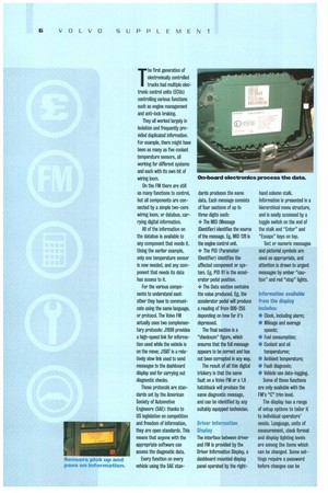
On the FM there are still as many functions to control, but all components are connected by a simple two-core wiring loom, or databus. carrying digital information.
All of the information on the databus is available to any component that needs it. Using the earlier example, only one temperature sensor is now needed, and any component that needs its data has access to it.
For the various components to understand each other they have to communicate using the same language, or protocol. The Volvo FM actually uses two complementary protocols: J1939 provides a high-speed link for information used while the vehicle is on the move; J1587 is a relatively slow fink used to send messages to the dashboard display and for carrying out diagnostic checks.
These protocols are standards set by the American Society of Automotive Engineers (SAE): thanks to US legislation on competition and freedom of information, they are open standards. This means that anyone with the appropriate software can access the diagnostic data.
Every function on every vehicle using the SAE sten dards produces the same data. Each message consists of four sections of up to three digits each: • The MID (Message IDentifier) identifies the source of the message. Eg, MID 128 is the engine control unit • The PID (Parameter IDentifier) identifies the affected component or system. Eg, PID 91 is the accelerator pedal position.
• The Data section contains the value produced. Eg, the accelerator pedal will produce a reading of from 000-255 depending on how far it's depressed.
The final section is a "checksum" figure, which ensures that the full message appears to be correct and has not been corrupted in any way.
The result of all this digital trickery is that the same fault on a Volvo FM or a 1.6 hatchback will produce the same diagnostic message, and can be identified by any suitably equipped technician.
Driver information Display The interface between driver and FM is provided by the Driver Information Display, a dashboard mounted display panel operated by the right hand column stalk. Information is presented in a hierarchical menu structure, and is easily accessed by a toggle switch on the end of the stalk and "Enter" and "Escape" keys on top.
Text or numeric messages and pictorial symbols are used as appropriate, and attention is drawn to urgent messages by amber "caution" and red "stop" lights.
Information available from the display includes:
• Clock, including alarm; • Mileage and average speeds: Fuel consumption; Coolant and oil temperatures;
* Ambient temperature; *0 Fault diagnosis; * Vehicle use data-logging.
Some of these functions are only available with the FM's "C" trim level.
The display has a range of setup options to tailor it to individual operators' needs. Language, units of measurement, clock format and display lighting levels are among the items which can be changed. Some settings require a password before changes can be