 1
1 2
2 3
3 4
4 5
5 6
6 7
7 8
8 9
9 10
10 11
11 12
12 13
13 14
14 15
15 16
16 17
17 18
18 19
19 20
20 21
21 22
22 23
23 24
24 25
25 26
26 27
27 28
28 29
29 30
30 31
31 32
32 33
33 34
34 35
35 36
36 37
37 38
38 39
39 40
40 41
41 42
42 43
43 44
44 45
45 46
46 47
47 48
48 49
49 50
50 51
51 52
52 53
53 54
54 55
55 56
56 57
57 58
58 59
59 60
60 61
61 62
62 63
63 64
64 65
65 66
66 67
67 68
68 69
69 70
70 71
71 72
72 73
73 74
74 75
75 76
76 77
77 78
78 79
79 80
80 81
81 82
82 83
83 84
84 85
85 86
86 87
87 88
88 89
89 90
90 91
91 92
92 93
93 94
94 95
95 96
96 97
97 98
98 99
99 100
100 101
101 102
102 103
103 104
104 105
105 106
106 107
107 108
108 109
109 110
110 111
111 112
112 113
113 114
114 115
115 116
116 117
117 118
118 119
119 120
120 121
121 122
122 123
123 124
124 125
125 126
126 127
127 128
128 129
129 130
130 131
131 132
132 133
133 134
134 135
135 136
136 137
137 138
138 139
139 140
140 141
141 142
142 143
143 144
144 145
145 146
146 147
147 148
148 149
149 150
150 151
151 152
152 153
153 154
154 155
155 156
156 157
157 158
158 159
159 160
160 161
161 162
162 163
163 164
164 165
165 166
166 167
167 168
168 169
169 170
170 171
171 172
172 173
173 174
174 175
175 176
176 177
177 178
178 179
179 180
180 181
181 182
182 183
183 184
184 185
185 186
186 187
187 188
188 189
189 190
190 191
191 192
192 193
193 194
194 195
195 196
196 197
197 198
198 199
199 200
200 201
201 202
202 203
203 204
204 205
205 206
206 207
207 208
208 209
209 210
210 211
211 212
212 213
213 214
214 215
215 216
216 217
217 218
218 219
219 220
220 221
221 222
222 223
223 224
224 225
225 226
226 227
227 228
228 229
229 230
230 231
231 232
232 233
233 234
234 235
235 236
236 237
237 238
238 239
239 240
240 241
241 242
242 243
243 244
244 245
245 246
246 247
247 248
248 249
249 250
250 251
251 252
252 253
253 254
254 255
255 256
256 257
257 258
258 259
259 260
260 261
261 262
262 263
263 264
264 An Opposed-piston Two-stroke Engine
Page 200
If you've noticed an error in this article please click here to report it so we can fix it.
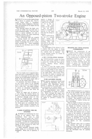
MOVELTY in two-stroke engine design I is shown in patent No. 723,111, which comes from J. Goodman, 7 Barnsley Road, Edgbaston, Birmingham, and discloses an oil engine having opposed pistons.
The drawing shows the basic unit, several of which may be built into a multi-cylindered engine. The unit cornprises a power cylinder (1) and a charging cylinder (2), each containing a pair of opposed pistons.
Their connecting rods arc coupled to rocking beams (3) mounted on stationary pivots and coupled by a further connecting rod (4) to a crankshaft assembly (5). Each crankshaft carries its own flywheel, one of which is shown at 6.
The two cranks run in opposite threedons and and each is connected by a chain drive to a bevel gear on one side of the casing; one of these gears is shown at 7. Both of the bevel gears mesh with a pinion on the output shaft (8).
In operation, the lower cylinder, on its out stroke, draws in air through ports 9 and on the in stroke forces it into a trunk (10). The upper cylinder is shown at maximum compression ready to receive the fuel from the injector (11).
When the upper pair of pistons is at out stroke, the exhaust leaves via ports 12, whilst the pre-compressed air is admitted through ports 13, thus giving a straight-through scavenge. The quantity of charging air is in excess of the upper-cylinder volume, so that the burnt gases are completely blown away. Water cooling is employed, the whole duplex cylinder assembly being jacketed.
EASIER STARTING FOR OIL ENGINES
A SCHEME for facilitating the starting of oil engines from cold. particularly those used in road vehicles, comes in patent No. 723,617 (A. Sanders, Redinnick House, Penzance, Cornwall). It relies for its functioning on the introduction of a small priming charge of fuel enriched by ether into the intake of the engine.
A small manually operated singlestroke pump (1) is mounted on the dashboard. When this is operated, it c58 squirts a charge of priming fuel through a pipe (2) to an injector (3) in the air intake. The chief feature of the scheme is that the starter switch is arranged to operate at the same time that the charge is injected.
This is achieved by the use of a second starter switch (4), which is piped to the priming tube and operated by the pressure generated by the hand pump. The acrvantage of the scheme is that it ensures that the engine is being turned over at the exact moment when the volatile fuel is injected. The normal starting switch (5) would be used for warm starts.
A BUS VENTILATING SYSTEM
AVENTILATING system for buses and other large vehicles is shown in patent No. 722,995 (R. Fone and A. Gernacy. HindleyHouse, Hindley Green. Wigan).
A duct (I) from the engine intake leads to an anti-resonance box (2) and thence to such points on the vehicle as need ventilating, such as the ceiling (3) of the upper deck. The system works all the time the engine is running, and at maximum power can displace over 200 Cu, ft. of air per minute.
TW723TUBULAR BODY FRAME ,878 (G. Sparshatt, Sea View, 0 patents, numbered 723,876 and
Providence Hill, Bursledon, Hants), disclose a scheme for using tube for the construction of vehicle bodies.
The pillars and transverse, hoops are made of large-diameter tube, whilst the longitudinals are made of smaller tube. Holes through the larger ones receive the smaller and the joints are made by welding. Capping units may be added to provide a surface for panelling. BRAKING BY USING ENGINE COMPRESSION
WHILST the compression of an engine is often regarded as having a braking action, in reality it has little effect, as most of the energy absorbed by the compression is returned on the succeeding expansion stroke. A compression-braking scheme in which energy is actually absorbed forms the subject of patent No. 722,568 (Slid werke Motoren-und Kraf twagenfabriken G.m.b.H., Essen, Germany).
The method proposed is to compress the air in the cylinder and then release it at top dead centre via the exhaust valve. The heat generated in the air is thus allowed to escape as fast as it is created. The scheme is most suited to two-stroke oil engines having uniflow scavenging.
Such an engine is shown in the drawing; the incoming air from the blower (1) charges an annular reservoir (2). This discharges into the cylinder at bottom stroke via a ring of ports (3), whilst the exhaust leaves via valve 4.
To brake, the exhaust valve is made to open at the moment of maximum compression, or at some earlier position if only partial braking is wanted. Control is provided by varying the phase angle of the camshaft; the patent gives details of the mechanism employed.
The patentee states that in modern large vehicles the limit of friction braking is being -approached and for descending long hills it is imperative that the developed heat be quickly dissipated.