


AN HYDRAULIC BRAKE IMPROVEMENT.
Page 28
If you've noticed an error in this article please click here to report it so we can fix it.
A Résumé of Recently Published Patents.
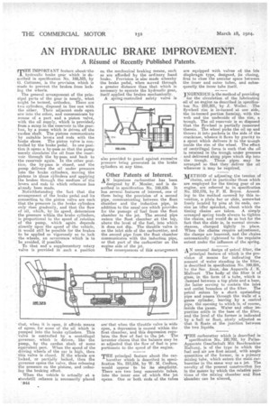
• rrulE IMPORTANT feature ahout;the
hydraulic brake gear which is de-scribed in specification No. 188,323, by .G. Cattaneo, is the provision which is :made to prevent the brakes from locking the wheels.
The general arrangement of the principal parts of the gear is nearly, what might be termed, orthodox. There are two cylinders, disposed in line one with the other. Their adjacent ends open ore into the other, and communicate by means of a port and a piston valve, with the oil supply, which is provided? from a sump in the reservoir in the gearbox, by a pump which is driven off the cardan shaft. The pistons communicate by suitable leveia and rode with the brake shoes. The piston valve is controlled by the brake pedal. In one position it opens a by-pass 80 that the pump merely circulates the oil from the reservoir through the by-pass and hack to the reservoir again. In the other position, the bypass is closed, and the pump delivers the oil under pressure into the brake cylinders, moving the pistons in those cylinders and applying the brakes through the medium of the levers and rods to which reference has already been made.
Notwithstanding the fact that the arrangement of the brake pedal and its connection to the piston valve are such
• that the pressure in the brake cylinders only rises gradually, and that the flow of oil, which, by its speed, determines the pressure within the brake cylinders, is proportional to the speed of rotation of the pump, which again depends " directly upon the speed of the vehicle, it would still be possible for the brakes to be applied so vigorously as to lock . the wheels, an occurrence which is to ..be avoided, if possible, •
To that end a supplementary rotary valve is provided in such a position
t sat, when it is open, it affoids means of egress for some of the oil which is pumped into the brake cylinders. This 'valve is controlled by a centrifugal governor, which is driven, like the pump, by the cardan shaft of some equivalent part. When the speed of this driving wheels of the car is• high, then -this valve is closed. If the wheels are 'locked, or partially locked, then the governor opens the valve, thus releasing the pressure on the pistons, and reducing the braking effort.
When the vehicle is actually at h standstill reliance is necessarily placed 'B44 on the mechanical braking means, such as are afforded by the ordinary hand brake. Provision is also made whereby the brake pedal, when moved through a greater distance than that which is necessary to operate the hydraulic gear, itself applied the brakes mechanically. A spring-contrulled safety valve is also provided to guard against excessive pressure being generated in the brake cylinders at any time.
Other Patents of Interest. AN ingenious carburetter has been designed by F. Monies', and is described in Specification No. 188,636. it has eeveral features of interest, one of them being the provision of a second pipe, communicating between the float chamber and the induction pipe, in addition to the usual one which provides for the passage of -fuel from the float chamber to the jet. The second pipe enters the float chamber ats the top, above the level of the fuel, into which it does not dip. The throttle valve is on the inlet side of the carburetter, and the second pipe from the float chamber Communicates with the induction pipe, or that part of the carburetter on the engine side of the jet.
The consequences of this arrangement are' that when the throttle valve is wide open, a depression is caused within the float chamber, and this depression regulates the flow of fuel to the jet. The inventor claims that the balance may be eo adjusted that the flow of fuel is proportionate to the speed of the engine.
"THE principal feature about the car huretter which is described in specification No. 210,556, by W. M. Crofton; would appear to be it simplicity. There are two • long concentric tubes. into the inner one 0g which /the 'jet opens. One or both ends of the tubes
are equipped with valves De the lies diaphragm type, designed, en closing, first to close the annular space between the inner and outer tubes, and subsequently the inner tube itself. • jNGENIOUS is the method of providing
for the circulation of the lubricating oil of an engine as described in specificaton No. 210,501, by .I. Weller. The flywheel rim is in-turned at one side, the in-turned portion forming, with the web and the underside of the rim, a trough. The oil reservoir is so disposed that the flywheel is partially immersed therein. The wheel picks the oil up and throws it into pockets in the side of the crankcase, whence it flows by gravity to a spout which delivers it to the' trough inside the rim a the wheel. The effect of centrifngal force is such that the oil is retained in the trough under pressure and delivered along pipes which dip into the trough. These pipes may be arranged so that they deliver the oil wherever it may be required.
METHOD of adjusting the tension of chains, and in particular those which are employed for the timing gear of an engine, are referred to in specification No. 210,578, by h'e H. Royce. According to the method covered by this invention, a plain bar or slide, somewhat freely located by pins at its ends, carries en idler sprocket, about which the timing chains are taken. A simply arranged spring tends always to tighten the chains, and would do so but for the fact that the slide is, in normal circumstances, clamped tightly in place. When the chains require adjustment, the clamps are loosened, and the cheins automatically tightened to the requisite extent under the influence of the spring
.A N unusual design of petrol filter, the principal feature of which is the provision ef means for indicating the amount of water standing in the filter, is described in specification No. 199436, be the Soc. Anon. des Appareils J.: B. Maliveee The body of the filter is of glass, in the form of a tube, which is damped between a top plate and a_baeo, :he latter serving to contain the inlet and outlet branches of the filter. The petrel enters by a short upstanding pipe and lenses through the walls of a gauze cylinder, leaving by a central pipe, the opening to which is, of course, inside the gauze. Water and other impurities settle in the base of the filter, and the level of the former is indicated by a ball or float, nicely adjustedBO that it floats at the junction between the two liquids.
THE carburetter which is described in specification No. 192,702, by PallasApparate Gesellachaft Mit Beschrankter Haftung, is of the type in which the fuel and air are first mixed, with ample quantities of the former, in a Ternary mixing tube, which enters the main carburettor in the same way as a jet. The novelty of the present eonstruetion lies in the means by -which the relative positions of the mixing chamber and• float 'chamber can be altered,