


Patents Completed.
Page 22
If you've noticed an error in this article please click here to report it so we can fix it.
Napier and Zenith Carburetters. Daimler Brake. Peugeot Valve-gear.
Copies of complete specifications of the patents published on this page can be obtained from the Sales Branch, Patent Office, Holborn, WC., at the cost of sixpence for each spectfication.
tion of air and fuel while the engine is running, and provision is made in this carburetter for accomplishing this by an extra rotary throttle.
As applied to the ordinary form of carburetter, in which the fuel inlet is at right angles to the air inlet, the size of these being varied simultaneously by a needle valve and piston, a perforated sleeve is arranged in the air inlet surrounding the floating piston so as to vary the air inlet without changing the opening of the fuel jet. This sleeve is arranged to be conta olled by a Bowden wire or other convenient device.
• THE DAIMLER, CO., LTD., and A. E. BEREIMAN, No. 10,765, dated 1st May, 1914.—One of the difficulties in designing brakes is that if the leverage is sufficiently great to enable . adequate power to be. obtained, the movement of the brake . shoes cannot then be made large enough to obtain sufficient clearance when the brake is in the off position. In this patent this difficulty ii overcome by providing a variable leverage, small at fir-sit until the shoo is just in contact with the dram, and then greater to enable the full power to be obtained.
The brake shoes are pivoted beside one another on eccentric pins and their other ends are forced apart by a cam. The cam is mounted on a shaft, which carries a lover bearing upon a cam-surface formed on the end of a bell crank. This bell crank is connected to the operating pedal, and the cam surface is so formed that the initial movement for expanding the brakes is rapid and the later movements slow.
The eccentric pins on which the shoes are pivoted are adjustable by means of sector racks controlled by a connection adjacent to the driver's seat. and are inclined to one another at any convenient angle according to other requirements of design. The camshaft is arranged over the exhaust valve, and operates it directly or through a AFekitig push-piece, which relieves side thrust on the valve stern.
The inlet-valve is operated from the same camshaft through a rocking lever, which is pivoted on a shaft lying between the two valves. This lever is made to operate directly on the valve-spindle, but it is preferred to use a.guided plunger or other similar device. The camshaft is driven from the crankshaft through a vertical shaft with bevel and helicaidal gears, and this vertical shaft is conveniently used for driving the magneto or any other mechanism required.
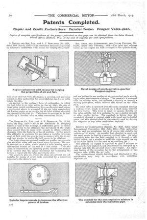
• SOCIETE DU CAEBURATEUR ZENITH, No. 2617, dated under International . Convention 19th July, 1913.—This carburetter can be used on aeroplanes, but is of course alto suitable for vehicles of all kinds. An annular float chamber is used, and the usual nozzle is fixed in a central vertical tube. An outer concentric tube has the fluid supplied to it through a calibrated orifice, and a number of small air inlets around the top of this•tube enable it to be used as an auxiliary jet.
The primary air supply is adjusted to give a mixture so rich as to he non-explosive, and this mixture is conveyed by a sloping tube into the air inlet close to the engine. An.importent feature of the invention lies in the arrangement of this mixture. tube within the air tube. "
Tho constructional details described and illustrated in this specification May vary in accordance with individual requirem_ nts.