Throttling
Page 62

If you've noticed an error in this article please click here to report it so we can fix it.
rtA SCHEME for utilizing the backpressure caused by throttling the engine exhaust is shown in patent No 707,438 (Oetiker-Motorbrernsen A.G., 22 Biristenstrasse, arich, Switzerland).
The patent refers to the construction
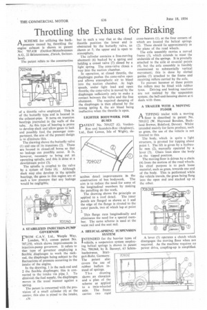
of a throttle valve employed. This is of the butterfly type and is located in the exhaust-pipe. It turns on trunnion bearings journaled in the walls of the tube. As this type of-bearing is prone to develop slack and allow-gases to leak and possibly foul the passenger compartment, the aim of the present design is to eliminate this.
The drawing shows the butterfly valve (1) and one of its trunnions (2). These are housed in closed-off, bores so that no leakage can possibly occur. It -is, however, necessary to bring out an operating spindle, and this is done at a downstream point (3).
The spindle is coupled to the valve by a system of links (4). Although slack may also develop in the spindle bearings, the gases in this region are at such a low pressure that any leakage would be negligible.
A STABILIZED INJECTION-PUMP GOVERNOR
FROM C.A.V. Ltd., Warple Way, London, W.3, comes patent No. 707,250, which shows improvements in injection-pump governors. It refers to that type of governor employing a flexible diaphragm to work the rackrod, the diaphragm being subject to the fluctuations of pressure occurring in the intake of the engine.
In the drawing, 1 is the rack-rod and 2 the flexible diaphragm; this is connected to the intake via pipe 3. To diminish the fuel supply, the diaphragm moves in the usual manner against a spring.
The patent is concerned with the provision of a small cylinder (4) at the centre; this also is piped to the intake, A36


