


the Exhaust for Braking
Page 62
If you've noticed an error in this article please click here to report it so we can fix it.
but in such a way that at the closed throttle position the lower end is obstructed by the butterfly valve, as shown at 5; the upper end is open to atmosphere.
The cylinder contains a free-moving abutment (6) backed by a spring and holding a coned valve (7) closed by a light spring. The cone-valve closes a way into the suction chamber.
In operation, at closed throttle, the diaphragm pushes the. cone-valve open and allows atmospheric air to bleed into the suction chamber. At high speeds, under light load and open throttle,-the cone-valve is moved by the diaphragm sufficiently only to make a contact between the valve and the free abutment. The required damping of the diaphragm is then effected by the strong spring 8, the air bleed being ineffective when the throttle is open.
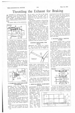
LIGHTER BODYWORK FOR BUSES
PATENT No. 709,027 (G. VerdonRoe and Saunders-Roe (Anglesey), Ltd., East Cowes, Isle of Wight), de
scribes detail improvements in the construction of bus bodywork. The aim is to reduce the need for some of the longitudinal members by making the panelling do the work.
The drawing shows the principle as
applied to a roof detail. The inner panels are flanged as shown at 1 and the edge of the flange is riveted to the outer panels, two of which lap at point 2.
This flange runs longitudinally and eliminates the need for a special member. The same scheme is used at the waist rail and the seat rail.
A HELICAL-SPRING SUSPENSION SYSTEM INTENDED for the heavier types of 1 vehicle, a suspension system employing helical springs is shown in patent No. 708,068, by B. Barenyi, 63 Sch8nbuchstrasse, Stuttgart-Rohr, Germany. The patent also covers the use of rubber buffers instead of springs.
The drawing shows an elevation and a pIan of the scheme as applied to a twin-wheeled axle. The frame carries two rigid cross-bearers (I), at the four corners of which are located the helical springs (2). These should lie approximately in the plane of the road wheels.
The axle assembly carries a curved frame (3), which extends to meet the underside of the springs. It is pivotally attached to the axle at co-axial points (4), but the axle assembly is forcibly constrained to substantially vertical movement; this is done by slotted guides (5) attached to the frame and receiving rollers carried by the axle.
To prevent hammer at these points the rollers may be fitted • with rubber tyres. Driving and braking reactions are not resisted by the suspension system; the ball-and-housing shown at 6 deals with these.
A TRAILER WITH A MOVING FLOOR
I-1 A TIPPING trailer with a moving
floor is described in patent No. 709,012 (W. Heywood Bowden, Buckland Brewer, Bideford, Devon). Whilst intended mainly for farm produce, such as grass, the use of the vehicle is not limited to this.
The body, which is quite a light structure, is pivoted for tipping about point I. The lift is given by a hydraulic ram (2), manually operated by a lever (3). Chain lines show the body in the tipped position.
The moving floor is driven by a chain (4) from the motion of the road wheels. Its chief purpose is to pack loose material, such as grass, towards one end of the body. This is performed while the vehicle travels, the grass being flung into the open end and stacked up at the other.