 1
1 2
2 3
3 4
4 5
5 6
6 7
7 8
8 9
9 10
10 11
11 12
12 13
13 14
14 15
15 16
16 17
17 18
18 19
19 20
20 21
21 22
22 23
23 24
24 25
25 26
26 27
27 28
28 29
29 30
30 31
31 32
32 33
33 34
34 35
35 36
36 37
37 38
38 39
39 40
40 41
41 42
42 43
43 44
44 45
45 46
46 47
47 48
48 49
49 50
50 51
51 52
52 53
53 54
54 55
55 56
56 57
57 58
58 59
59 60
60 61
61 62
62 63
63 64
64 65
65 66
66 67
67 68
68 69
69 70
70 71
71 72
72 73
73 74
74 75
75 76
76 77
77 78
78 79
79 80
80 81
81 82
82 83
83 84
84 85
85 86
86 87
87 88
88 89
89 90
90 91
91 92
92 93
93 94
94 95
95 96
96 97
97 98
98 99
99 100
100 101
101 102
102 103
103 104
104 105
105 106
106 107
107 108
108 109
109 110
110 111
111 112
112 113
113 114
114 115
115 116
116 117
117 118
118 119
119 120
120 121
121 122
122 123
123 124
124 125
125 126
126 127
127 128
128 129
129 130
130 131
131 132
132 133
133 134
134 135
135 136
136 137
137 138
138 139
139 140
140 141
141 142
142 143
143 144
144 145
145 146
146 147
147 148
148 149
149 150
150 151
151 152
152 153
153 154
154 155
155 156
156 157
157 158
158 159
159 160
160 161
161 162
162 163
163 164
164 165
165 166
166 167
167 168
168 169
169 170
170 171
171 172
172 173
173 174
174 175
175 176
176 177
177 178
178 179
179 180
180 181
181 182
182 183
183 184
184 185
185 186
186 187
187 188
188 189
189 190
190 191
191 192
192 193
193 194
194 195
195 196
196 197
197 198
198 199
199 200
200 A Striking 10-ToN SIX-WHEELER
Page 92
Page 93
Page 94
If you've noticed an error in this article please click here to report it so we can fix it.
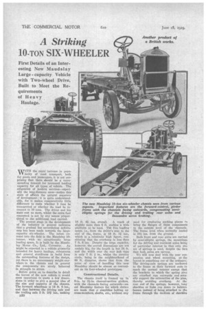
WWITH the rapid increase in popuV V larity of road transport, both for goods and passengers, it is not sur prising that there should be a cormsponding demand for increased loading
capacity for all types of vehicle. The exigencies of modern services—especially the long-distance ones—makes this state of affairs the natural sequence of development; it is quite understandable, for it makes comparatively little difference to costs whether 5 tons be transported or whether the load be increased to 10 tons. The driver and his Mate cost no more, whilst the extra fuel consumed is not by any means" proportional to ,the additional load carried.
• The present stage in the development of the industry in general indicates that a gradual" but nevertheless definite step has been made towards the largecapacity six-wheeler. The latest entrant into the field is the Maudslay 10tanner, with an exceptionally large loading space. It is built by the Mantis-, lay Motor Co., Ltd., Coventry. As might be expected in a vehicle primarily intended for heavy haulage, robustness and general sturdiness in build form the outstanding features of the design, yet there is no unnecessary weight anywhere in the 'chassis and in general the components are nicely balanced in strength to stress.
Before going on to describe in detail the layout of the new vehicle it would seem opportune to quote a few dimensions in order to give a general idea of the size and capacity of the chassis. The forward wheelbase is 14 ft. 6 ins., and that between the driving axle and the trailing axle 3 ft. 10i ins., making
D30
18 ft. 44 ins. overall. A track of
slightly more than 6 ft. enables a wide platform to be used. The free loading space, i.e., from the driver's seat to the end of the, frame, is 19 ft. 14 ins., which is a relatively 'high figure, considering that the overhang is less than 7 ft. 6 ins. Despite the large capacity, however, the overall dimensions are not unduly big, for the length is but 24 ft. and the width over the rear hub caps is only 7 ft. in., whilst the turning circle, being in the neighbourhood of 60 ft. diameter, shows that from the point of view of handling this new Maudslay should be almost as convenient as it four-wheeled prototypes.
Constructional Details.
The chassis itself is framed up in 8-in. by 24.-in. channel-section girders, with the channels facing outwards—au old Matidslay feature for which claims are made that it simplifies bolting up cross-members, shafts, etc., without any need for employing pricking pieces to bring the flanges of these components to the outside level of the channels. The frame level when normally loaded is 384 ins, from the ground.
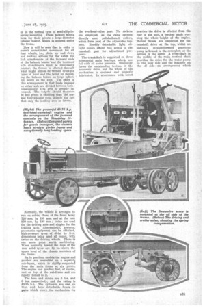
Both front and rear axles are carried by semi-elliptic springs, the mountings for the driving and -rearmost axles being of particular interest in that only one set of springs is used, despite the fact that both axles are sprung.
We will now deal with the rear suspension and wheel mounting, as the layout is something out of the ordinary. The driving-axle springs are anchored to the frame at their, forward ends in much the normal manner except that the brackets to which the spring pins are ettached run outwards and actually support the extremities of the pins, thereby avoiding overhang. At the rear end of the springs, however, long shackles or links run down to balance beams, instead of being attached to the frame through the medium of shackles
as in the normal type of semi-ellipticspring mounting. These balanee beams have for their pivots a large-diameter tubular bearer, which is secured under the frame.
Now it will be seen that in order to permit unrestricted movement for all four wheel; i.e., plain up and down and rocking actionsfor the axles, the link attachments at the forward ends of the balance beams and the rearmostaxle attachments must be universally jointed ; the former is effected through -what might almost be. termed cross-pin types of joint and the latter by mounting the balance beams on large spherical joints on the axle. The effect of this arrangement is that loads imposed on either axle are divided between both ; consequently tyre grip is greatly increased. The vehjcle should therefore be lesi prone to skidding than the normal four-wheeled type, despite the fact that only the leading axle is driven.
Normally, the vehicle is arranged to run on solids, those at the front being 720 mm. by 180 mm. and at the rear 850 mm. by 180 mm.; twins are used for the driving axle and singles for the trailing axle. Alternatively; however, pneumatic equipment can be obtained, high-pressure tyres of 40-in. by 8-in. dimensions being used all, round, with twins on the driving wheels. 7'here is one more point worth mentioning. When normally loaded the tops of the rear solid tyres are 1i in. above the upper level of the chassis members of the frame;
As in previous models the engine and gearbox are assembled on Et separate sub-frame, which is rigidly suspended from the main frame at six points. The engine and gearbox feet, of course, rest on top of the sub-frame and are rigidly bolted to it.
The bore and stroke are 5 ins. and 6 ins. respectively, and the rating is 40-75 h.p. The cylinders are cast en bloc, and haye detachable heeds in pairs which carry the mechanism for
the overhead-valve gear. No rockers are employed, as the cams operate directly over polished-steel rollers, which form part of the adjustable .tappets. Readily detachable light oiltight covers afford free access to the camshaft gear for adjustment purposes.
The crankshaft is supported on three substantial main bearings, which are fed with oil under pressure. Simplicity forms the outstanding feature of the accessory drive, and the whole of the _reechanismh is enclosed and properly lubricated. In -accordance with latest practice the drive is effected from the rear of the unit, a vertical shaft running the whole height of the engine. Helical bevels are employed for the camshaft drive at the top, whilst an ordinary straightforward gear-type pump is housed in the coverplate at the bottom of the sump. A cross-shaft in the middle of the main vertical shaft provides the drive for the water pump on the near side and the magneto on the off side—an arrangement which brings these two components into particularly accessible positions. In passing, it might be mentioned that at the top of the vertical-shaft housing a sliding joint is arranged to permit of rapid dismantling when decarbonization is necessary.
The oil pump is built into the bottom cover plate of the sump and can be readily dismantled for examination or repair ; also, it is constantly primed.
An external pipe runs from the pump to a double-gauze filter—also accessibly mounted on the off side of the crank chamber—thence to a four-way piece which is situated midway along the crankcase. Further external piping leads the oil into the main journals of the crankshaft and then by passages in this component to the big-end bearings of the connecting rods.
An external pipe-line leads lubricant direct to all the camshaft bearings and the driving gears. The " drain down into the crankcase is effected partly by an external pipe and partly through the medium of the vertical-shaft casing, the latter passage, of course, providing efficient lubrication en route for the gears on the cross-shaft and the main drive from the crankshaft.
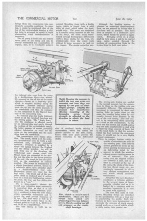
The transmission next claims attention. The clutch, which is of the ordinary inverted-cone type, is really a selfcontained unit, although externally mounted. Pressure is supplied by a single coil spring between the flywheel and the driven member. As will be seen from one of the drawings, the withdrawal gear presses apart two thrust races, one connected to the driving and the other to the driven portions of the unit ; the result is that end pressure on the crankshaft is entirely avoided. The power is transmitted to a simple four-speed gearbox, thence by a relatively short, open propeller shaft to a double-reduction rear axle. Mechanical joints are used for the .final drive. The front end of the propeller shaft is enclosed and it articulates on a four-star ball-bearing universal joint ; the rear end has sliding dies housed in a " pot."
On a large-capacity chassis the overall gear reduction must necessarily be somewhat high so that it is not surprising that double-reduction gearing is employed to keep the axle casing within reasonable dimensions and to permit the good ground clearance of 11 ins. The final ratio is 8.25 to 1, which brings the overall ratios on the indirect gears to 41.25 to 1, 23.75 to 1 and 14.25 to 1 respectively.
The axle casing is built up on D32 original Mandslay lines, with a double banjo, which is forged from a solid billet of steel, which takes the deadweight only. The gears are contained in a circular casing mounted on the top of the banjo, the drive being transmitted through floating-type differential shafts ; these shafts, by the way, are withdrawable from the wheel hubs without it being necessary to jack up the chassis. The double reduction con sists of overhead bevels driving a countershaft, which lies across the chassis parallel to the axle casing. Extra wide spur gears provide the second reduction to the differential shafts. ,
Although the braking -systeru is planned on somewhat unconventional lines, we are assured by drivers that it functions well in practice. The hand lever is coupled to a Dewandre servo motor, which boosts the power of appli cation. Swinging levers on a crossshaft in turn cause a pull to be exerted upon cables coupled through the medium of compensating links to the brakes fitted to both rear axles.
The driving-axle brakes are applied in the normal manner, but the connections to those on the trailing axle are necessarily different. The articulating movement is transferred by short connecting links to brake arms on the cams, the reaction being taken by universally jointed links situated at the top of the axle casing. The foot control is by contracting shoes operating on a drum on the transmission. As the shoes are well ribbed and of stiff section they are able satisfactorily to deal with a relatively large amount of heat, but as the hand brake is that for service, whilst the foot controls the emergency brake, it should not be a very highly stressed component There is another feature which is worthy of attention—we refer to the steering gear. This follows normal practice in so far as the actual gearing is concerned, but an interesting point is the manner in which the steeringcolumn support casting serves as an oil reservoir. The gear casing and the support column are virtually a unit, and as a filler is provided at the top of the casing the whole of the steering box, thrust races, etc., are constantly immersed in oil—a very efficient arrangement and one which should facilitate maintenance.
Altogether this new Maudslay constitutes a welcome addition to the present range of largecapacity vehicles, and as it is backed by a company with an excellent reputation it is sure to meet with approval.
The fact that units of wellknown Maudslay design are embodied in the specification will go a long way to popularizing the model. Such new features as have been incorporated are obviously the outcome of much experimental work on a type of vehicle which is daily coming into greater use.