


Patents Completed.
Page 22
If you've noticed an error in this article please click here to report it so we can fix it.
CLUTCH.—Daimler Motoren Gesellschaft.—No. 11,407/07, dated (under Convention) 16th May, 1906.—This invention relates to clutches of the type in which the driven member takes up a gradual connection with the driving member. The fly wheel (a) is bored to receive the driving cone member of the clutch which comprises an inner cone member (b) and an outer cone member (61), both being rigidly connected to the fly wheel (a).
The driven member of the clutch, which consists of a casting (c) mounted on the driven shaft, is provided with an inner cone member (d) and an outer cone member (dl). Brake rings (f, fl) are loosely mounted on the cone members (d, di) ; these are held in position by clamping rings (g, gl). When the driven member (e) of the clutch is advanced into engagement with the driving member by means of the spiral spring, the brake-ring (f1) of the outer cone member engages the cone member (61) and, on further advancement, the brake-ring (f) on the inner cone member (d) will engage the cone member (b). It will be seen that, in this way, a certain amount of slip will take place on the brake rings (f, p) before a positive drive is obtained.
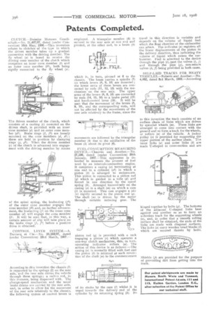
CONTROL LEVER SYSTEM.—A. Darracq et Cie.—No. 28,263/07, dated (under Convention) 23rd March, 1907.— According to this invention the chassis (1) is supported by the springs (2) on the rear axle, and the rear axle drives the vehicle through these springs ; a radius rod, in this instance, being dispensed with. The .change-speed mechanism and the usual brake drums are carried by the rear axle, and, in order to allow for the movement of the rear axle relatively to the chassis, the following system of control levers is
employed. A triangular member (4) is secured to the rear axle at one end and pivoted, at the other end, to a beam (5) which is, in turn, pivoted at 6 to the chassis. The beam carries a spindle (7) on which levers (8, 9, 10) are mounted ; the lower arms of these levers are connected by rods (11, 12, 13) with the mechanism on the rear axle. The upper arms of the levers (8, 9, 10) are connected by rods (14, 15, 16) to a brake pedal (17) and hand-control lever (18). It will be seen that the movement of the levers (8, 9, 10), and the corresponding rods, will not be affected by the movements of the rear axle relatively to the frame, since the movements are followed by the triangular member (4) due to the oscillation of the beam (5) about its pivot (6).
FUEL-CONSUMPTION MEASURING DEVICE.—Chauvin and Another.—No. 27,536, dated (under Convention) 39th January, 1907.—This apparatus is intended to measure the amount of fuel used by an internal-combustion engine. It comprises a casing (a) terminating at one end in a cylinder (al) in which a piston (b) is arranged to reciprocate. This piston is connected to a piston rod (q) which is guided in a tube (d) and forced in one direction by the spiral spring (k). Arranged transversely on the casing (a) is a shaft (m) on which a cam (1) is mounted. This cam engages a pin (n) rigidly secured to the piston rod (q). The shaft (m) is driven by the motor through suitable reducing gear. The piston rod (q) is provided with a rack engaging a pinion (r) which operates a one-way clutch mechanism, this, in turn, operating indicator rollers (a). The action of this device is as follows :—The casing (a) is normally filled with fuel and the piston (b) is returned at each revolt:tion of the shaft (m) to the commencement of its stroke by the cam (1) whilst it is urged towards the delivery end of the cylinder by its returning spring (k). Its travel in this direction is variable and depends on the volume of liquid fuel which the float chamber of the carburetter can admit. The indicator (u) registers all the linear displacements of the piston in the delivery direction, thus indicating the volume of liquid which enters the carburetter. Fuel is admitted to the device through the pipe (e), past the valves (1, j) and through the pipe (g), non-return valves (h, f) being provided in both cases.
SELF-LAID TRACKS FOR HEAVY VEHICLES.—Roberts and Another.—No. 4,862, dated 3rd March, 1908.—According
to this invention the track consists of an endless chain of links which are driven by sprocket wheels (m). These links are arranged to come into contact with the ground and so form a track for the wheels, or rollers (a) of the vehicle. A jockey pulley (a) is provided for supporting the upper portion of the endless chain. The inner links (a) and outer links (b) are made U-shaped in cross-section and are hinged together by bolts (g). The bottoms of the adjacent U-shaped links bear against one another so as to form an unbroken track for the supporting wheels (a), and, in order that a smooth rolling surface shall be obtained, the ends of the links are made with diagonal surfaces. The links (a) carry wooden tread blocks (1) which are secured thereto by bolts.
Shields (p) are provided for the purpose of preventing dirt from getting into the track.