


An Improved Ignition Coil.
Page 14
Page 15
If you've noticed an error in this article please click here to report it so we can fix it.
A Fitting that will stand up to the Rough Usage of Commercial-vehicle Work.
In the early days of electric ignition on multi-cylindered engines, each cylinder was provided with a separate coil ; each coil was fitted with a trembler and condenser, and thus constituted a complete and separate unit. Needless to state, synchronism with such devices was almost impossible. Wilson and Pilcher's invention of the single-trembler multicylinder coil was hailed by many in the motor trade as offering a remedy for all the troubles which had been experienced during the time that the separate-unit coils had been in use synchronism was rendered possible, faults were more easy to locate, and, generally, the improved coil was looked upon as a great advance on anything which had, up to that time, been introduced. The next step was the system which is now very much in vogue—the single coil, used in conjunction with a high-tension distributor for any number of cylinders. With this arrangement, synchronism could be obtained with ease, but the sluggishness, or lag, of the trembler placed a limit on the speed at which an engine so fitted could be run. For commercial vehicles, this fact may, to many, appear in the light of an advantage, but it must be remembered that there are many vehicles in use at the present time, which, although fitted with high-speed engines, are excellent machines so far as their reliability is concerned. A sluggish coil, when used on such a vehicle, would prevent the engine giving out its maximum power, as may be gathered from an article on, inter alia, the effect of lag in an ignition coil, which appeared in "THE COMMERCIAL MOTOR" of the 6th February last.
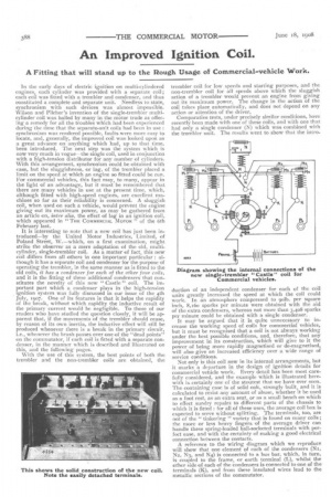
It is interesting to note that a new coil has just been introduced—by the United Motor Industries, Limited, of Poland Street, W.—which, on a first examination, might strike the observer as a mere adaptation of the old, multicylinder, single-trembler coil. As a matter of fact, this new coil differs from all others in one important particular : although it has a separate coil and condenser for the purpose of operating the trembler, in the same manner as is fitted to the old coils, it has a condenser for each of the other four coils, and it is the fitting of these additional condensers that constitutes the novelty of this new " Castle " coil. The important part which a condenser plays in the high-tension ignition system was fully discussed in our issue of the 4th July, 1907. One of its features is that it helps the rapidity of the break, without which rapidity the inductive result of the primary current would be negligible. To those of our readers who have studied the question closely, it will be apparent that, if the movements of the trembler should cease, by reason of its own inertia, the inductive effect will still be produced whenever there is a break in the primary circuit, i.e., whenever the brush passes over one of the "dead points" on the commutator, if each coil is fitted with a separate condenser, in the manner which is described and illustrated on this, and the following pages.
With the use of this system, the best points of both the trembler and the non-trembler coils are obtained, the trembler coil for low speeds and starting purposes, and the non-trembler coil for all speeds above which the sluggish action of a trembler would prevent an engine from giving out its maximum power. The change in the action of the coil takes place automatically, and does not depend on any action or attention of the driver.
Comparative tests, under precisely similar conditions, have recently been made with one of these coils, and with one that had only a single condenser (N) which was combined with the trembler unit. The results went to show that the intro
duction of an independent condenser for each of the coil units greatly increased the speed at which the coil could work. In an atmosphere compressed to yolk>. per square inch, 8,16o sparks per minute were obtained with the aid of the extra condensers, whereas not more than 3,408 sparks per minute could be obtained with a single condenser..
It may be argued that it is quite unnecessary to increase the working Teed of coils for commercial vehicles, but it must be recognised that a coil is not always working under the best possible conditions, and, therefore, that any improvement in its construction, which will give to it the power of being more rapidly magnetised or de-magnetised, will also give an increased efficiency over a wide range of service conditions.
Not only is this coil new in its internal arrangements, but it marks a departure in the design of ignition details for commercial vehicle work. Every detail has been most carefully considered, and the example which is illustrated herewith is certainly one of the stoutest that we have ever seen. The containing case is of solid oak, strongly built, and it is i calculated to resist any amount of abuse, whether t be used as a foot rest, as an extra seat, or as a small bench on which to effect sundry repairs to different parts of the chassis to which it is fitted : for all of these uses, the average coil box is expected to serve without splitting. The terminals, too, are not of the " tinkering " variety that is found on many coils ; the more or less heavy fingers of the average driver can handle these spring-loaded ball-socketed terminals with perfect ease, and with the certainty of making a good electrical connection between the contacts.
A reference to the wiring diagram which we reproduce will show that one element of each of the condensers (Ni, Na, N3, and N4) is connected to a bus bar, which, in turn, is coupled to the frame, or earth terminal (L), whilst the other side of each of the condensers is connected to one of the terminals (K), and from these insulated wires lead to the metallic sections of the commutator.
The coil box encloses five units : the centre one contains the trembler and its electro magnet; and, at each side of this, there are two working-coil units. The trembler is one which is, normally, designed to give the best results at moderate speeds; it is provided with a very simple form of adjustment, and one that is at the same time sensitive and positive. The current enters the trembler unit by way of the terminal (H) and, after traversing the magnet windings, leaves the centre unit by way of the cut-out terminal (NI); it is then conducted, by the bus bar (J), to each of the working coils, through the cut-out connectors (Mi, M2, M3, and M4). The four sections of the commutator are connected to the terminals (K, K, K, K.), which are to be seen on the tops of the coils. The return, or earth, connections are made through the screws and wing nuts by which each unit is secured within the case ; the screws pass through the bottom of the case, and the wing nuts bring them into close electrical contact with a bus bar to which the terminal (L) is attached. The high-tension wires to the sparking plugs are led from the terminals (Pi, P2, P3, and P4); fitted into the back of each of these terminals is a spring-loaded brass ball, that makes contact with a small brass plate which is let into the front wall of each unit, and to these plates one end of the high-tension coil winding is attached. This form of construction enables any one of the units to be withdrawn from the case without the necessity of disturbing any of the wiring : it is only necessary to unscrew the wing nut, and to withdraw the cut-out at the top of the. unit ; the latter may then be withdrawn and, if necessary, replaced by another one. All the coil units are interchangeable, as also are all the solidly-made and well-insulated cable ends, or connectors, which are shown in the illustration standing on the lid of the case.
Another of our illustrations shows a new commutator that this company has designed for use with the coil which we have above described. Like the coil, this new interruptor is made of such generous proportions that it is not likely to suffer much at the hands of a clumsy driver. The case is made of solid bronze, and the contact pieces (C, C, C, C), to which the terminals (D, D, D, D) are electrically connected, are made of hard steel. The insulating medium is red fibre, but, in order to prevent the rapid wear which would take place on the fibre if the brush, or wiper, were allowed to slide over the surface of this comparatively soft material, the spaces between the contact sections are almost completely faced by the steel sectors (E, E, E, E). These intermediate pieces are, of course, completely insulated from the four working contacts, and from all other metallic parts of the interruptor Or its case. Their object is to present an almost continuous steel track for the wiper to slide upon, and to prevent the grooving of the fibre disc. When the fibre surface becomes worn into deep grooves, by reason of the rubbing action of the wiper, the make-and-break action becomes rather erratic, on account of the fact that the contact sectors stand "proud " of the fibre surface, leaving their high edges to be chipped off by the rotating wiper ; the small particles of metal thus separated become rolled into the surface of the fibre, until the undesirable condition of practical continuity exists, and " shorting" is the unpleasant and troublesome result.
The inner ring (A) is connected to the terminal (B), whence the return current is taken through a wire to a fixed part of the engine frame. The arm (G) which carries the brushes, or wipers (At, and BO, is mounted on the end of a spindle that is driven at one half of the speed of the engine crankshaft. The wipers, which are spring loaded, make close contact with the ring (A), and one or other of the sections to which the low-tension leads are attached.
A neat brass cover fits over the top of the case, and completely encloses all the working parts, which are thus protected from dust and moisture, whilst a couple of ingenious spring catches effectively prevent the cover from working loose or being shaken off.
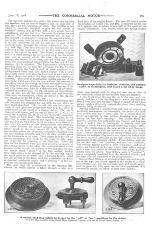
Having obtained a stoutly-made coil, and an almost unbreakable commutator, or interruptor, the owner of a business vehicle will say—" Now, give me a switch that my driver can operate by foot without knocking it to pieces during the first day's working." The United Motor Industries, Limited, has anticipated his request, and has produced a switch that is thoroughly in keeping with the fittings to which we have already drawn our readers' attention. The construction of this new switch is well illustrated by the three views which are reproduced at the foot of this page : that on the left shows the strong bronze cover which encloses the contacts; the centre one shows the switch with the cover removed; and that on the right shows the general appearance of the complete switch. Three definite positions are provided—one "OFF "position, and two" ce,r " positions. The vertical spindle carries a short cross-piece, and small rollers are mounted on its outer ends; these rollers engage with a face cam, which is divided into four parts, each insulated from the others. One of these parts is "earthed one is completely insulated from the electrical circuit ; and the other two are connected to the accumulators.
None of these fittings, on account of their size and weight, are of the type that would appeal to the owner of a highclass pleasure car, but, for real hard wear and rough usage, such as generally falls upon the electrical equipment of a commercial vehicle, we know of none more suitable.