


Patents Completed.
Page 26
If you've noticed an error in this article please click here to report it so we can fix it.
NON-SKID DEVICE. — Alder.— No. 28,313, dated 12th December, 1006.— Rubber wheels (I) are pressed against the surface of the road by a pneumatic piston, worked by compressed air from a cylinder, which is charged by a pump worked by the engine. The action is Controlled by a trailer (A) which runs in line with the vehicle, but, on departing from a straight line, as when side-slip occurs, the trailer (A) turns on the pivot (C) and opens the valve (E) which admits compressed air into the chamber (M) and so forces the wheels (I) against the surface of the road to prevent the side-slip.
VEHICLE SPRINGS.— Cocker.— No. 22,582, dated 12th October, 1906.—This invention relates to an improved clip for bolding the springs of a vehicle to the axle. It consists of a base (A), having side plates (B), which terminate in bolts (C). The upper face of the base (A) is concave so as to bear against the convex bottom of the springs (5). The plates of the spring (5) have indentations (E) which register with one another, and so prevent longitudinal displacement of the spring. By screwing the nut (D) down on to the plate (F) the spring is held fast in position.
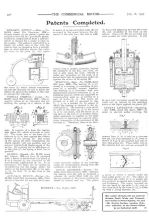
BRAKES.—Bassett.—No. 17,570, dated 3rd August, 1906.—A lorry is provided with a series of brake-shoes (A), fitted at B to a bracket (I) and connected to the lorry through toggle-joints (P, K). J. an emergency, this brake can be applied by straightening out the toggle, either by means of the hand-wheel (D) at the rear, or by the lever (N) at the front of the vehicle.
ANTI-SKID DEVICE.—Barber.—No. 21,248, dated 25th September, 1906.—This device is intended for use with twin tires. A series of spring-controlled bolts (3) are arranged in the space between the elements of the twin tire ; the bolt is suffi ciently long to project, normally, beyond the periphery of the tire, and, thus, obtain a grip upon the road. Should it strike any projection on the road, it is forced back into its supporting socket (1) against the action of its spring (6).
BEARINGS.—Mair.—No. 14,158, dated 20th June, 1906.—The bearing (b) is enclosed in a housing (c) consisting of two parts (d, e) suitably secured together. The housing (c) is furnished • with two diametrically-opposed trunnions (I, f) of spherical contour, which are supported in corresponding seats (g, g) formed in a pair of levers (h, h). The levers are pivoted on a bolt (0 mounted in lugs (j, j, j) on a bracket (k), by means of which the bearing is secured in the desired position. The housing (a) can swivel of itself in the seats (g, g) of the levers (h, h) in one plane, and the levers (h, h) can turn on the bolt (1) in another plane, either separately or together in the same direction, or separately in opposite directions, irrespective of the movement of the housing (c). Therefore, there is an abso lutely universal motion of the bearings under all circumstances arising from the condition of the shaft (a).
SHOCK ABSORBER.— Byrom.— No. 1,811, dated 24th January, 1907-.—Between the chassis and the axle is mounted a cylinder (A) partly filled with oil, and having conduits (J, II) communicating between its bottom and top. , The piston
(E) has a rod extending through the cover (B), and connected to the body of the vehicle. Spaces (N, M) are provided and these contain air under pressure. It will be seen that concussion caused by uneven roads will be reduced by the retarding action of the liquid against the piston (E).
CEMENT PAVEMENTS.—Kieserling. —No. 7,988, dated 5th April, 1907.—In order to prevent undue cracking, the
cement floor (b, b].) is laid on a concrete bed (a), and iron members (e, el), bent as shown in Fig. 2, are inserted and rest on iron base-plates (h). These latter rest on the concrete bed (a), and are arranged in a cavity (1) which is formed under the bent metal plates (k, kl). The object of providing the cavity (1) is to enable the iron plate (h) to expand and contract with. out hindrance. The space, bounded on the one hand by the rails (a, a1), and on the other hand by the channel (1), is filled up with a luting material (m).