


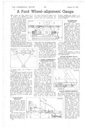
A Ford Wheel-alignment Gauge T o enable the front wheels of
Page 58
If you've noticed an error in this article please click here to report it so we can fix it.
a vehicle to be adjusted to a high Jegree of acccuracy in a minimum of time, is the aim of a device shown by the Ford Motor Co., Ltd., 88, Regent Street, London, W.I, in patent No. 66L795. A ,-point emphasized in the patent is that static tests are of little use:. to be accurate they must be made under running conditions, and this the machine is capable of doing.
The • drawing shows enough of the construction to make the principle clear. The apparafus is mounted below ' floor-level and, the vehicle runs on to it so that the front wheels (1) drop to make contact with the gauging rollers (2). These rollers/-of which there are tt,vo, provide the "driving power, eaeh being belted to 661795 an electric motor, shown at 3. one of which is The roller-motor assembly is carried in a cradle which is free to rock on trunnions (4-4), but is biased into an upright position by a weight (5). All this is duplicated on the other side to deal with the other front wheel.
In operation, the rollers are set running to drive the wheels. If the two wheels have any divergence from the parallel, the two trunnioned frames are caused to tip one way or the other;
The amount of tip is electrically measured and works an indicator in a position in which it can readily be seen by the operator. Space is left under the floor for mechanics to make such adjustments as may be found necessary.
RAPID ENGINE REMOVAL IN patent No. 661,658, I H. van Doorne, Deurne, Holland, covers a method of so mounting an engine in the chassis that it can be " removed in a few minutes without having to use any tools to effect disconnections.
The drawing shows the unit in its outermost position, the normal position being indicated at 1, which is the radiator shell. A40 The engine sub-frame (2) slides in the main frame on rollers (3 and 4). The propeller shaft (5) is made fully tele.
scopic and it has self-engaging splines.
Accelerator and clutch pedals have Self-connecting couplings, as have the gear lever and telescopic exhaust pipe. The securing means is a hand operated locking lever (6).
To permit the engine to be runfor'test purposes when in the ." out" position, the fuel, electric leads and compressed air are carried in flexible pipes, one of which is shown at 7.
A SIMPLE INDEPENDENT SUSPENSION SYSTEM
A DESIGN for an indepenPI dent suspension system employing " wishbone " links is dealt with in patent No. 660,443 (George Salter and Co., Ltd., 114, High Street, West Bromwich). Torsion rods are used, but they are short, thus reducing the length of chassis that is subject to spring stresses.
Referring to the drawing, which shows a plan view, the torsion rods (1) are of square section, and are buitt up from laminations, so that, the assembly is really a leaf-spring subjected to twisting instead of bending stresses. The spring is firmly anchored to the frame by a central bracket (2), whilst , outer brackets (3) form" the pivot bearings for the wishbone (4).
A feature of the scheme is the high factor of safety; should one of the leaves break, the others would still function, enabling the vehicle to be driven Until such time as proper repairs could be effected.
AN IMPROVED TIP-WAGON
PATENT No. 660,783, which. comes from the 'Anthony Company, Streater, . Illinois, U.S.A., shows a design for a hydraulicpowered tipping body. The chief feature is the linkage connecting the hydraulic ram with the body; this employs parts which, although --(St capable of giving a high
angle of tip, do not, in the retracted position, project appreciably below the frame. As the piston rod (1) emerges from the hydraulic cylinder, -its end commences to move in an arc constrained by lever 2. As this member swings, it pulls on a link (3) and so lifts a second lever (4). The latter is coupled by link 5 to a pivot (6).
As the motion continues, it tends to straighten-mit members 4 and 5 to the fully tipped position.
BETTER WEARING RINGS IMPROVEMENTS in piston rings form the subject of patent No. 662,213, which comes from the British Piston Ring Co., Ltd., Coventrcr. The aim is to promote the durability of the ring, and to this end the rubbing face is coated with chromium. The top and bottom faces of the ring are hardened.
POWER-ASSISTED STEERING
ASERVO steering system is shown in patent No. 662,724, by Bendix Aviation Corporation, South Bend,
Indiana, U.S.A. A feature of the scheme is that, for small movements, the steering wheel works the steering direct, power assistance being brought in only when the wheels are moved through a large angle. Hydraulic power is the medium used, steeringwheel movement operating the control valve. This valve comes into action only when tit steering reaches a given leftor right-handed deflection.