


Frame• Heig New Flat-e
Page 42
Page 43
Page 44
If you've noticed an error in this article please click here to report it so we can fix it.
Reduced in a lined Chassis
Sweden Enters the Market for Underfloor-engined Chassis with z. Model Specially Designed for Low Platform Levels Pancake Engine has Fluid Coupling and Pre-selective Gearbox Attached as a Unit
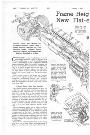
COMPETITION ampng manufacturers of underfloor-engined passenger chassis -is: increased by a . new model .made by ,A.13. Volvo;: ibothenbUrg, Sweden. The comparly setout to ' provide AL.pancake. engine of minimum depth for amidship mounting, and the main frame members are planned to permit shallow risers to be used at all three doors of the body. The platform height of .underfloor-engined buses and coaches has been subject to world criticism, and the Volvo scores in this respect, being lower than contemporary models.
Other notable details in the design are a 9.6-litre direct-injection engine having an output of 153 b.h.p., air-operated pre-selective gearbox and hydraulic coupling, and a hypoid-drive axle with transmissiondrum parking brake taking effect on a drum attached to the input shaft.
Cylinder Block Under Side Member The cylinder block has been arranged to fit under one of the frame side members, with the crankshaft and transmission offset approximately 5 ins, from the frame centre line. A gear drive to the camshaft and fuel pump, together with a flat-base dry sump, are also instrumental in reducing the height of the power unit within the chassis frame. By far the deepest part of the engine is the flywheel housing, measuring 22i ins. in overall diameter, but this is tucked away inside the chassis to provide a ground clearance of 91 ins.. with 11.00 by 20-in. tyres fitted, which • are standard equipment.
The six-c.ylindered engine has an integral cast-iron crankcase and cylinder block fitted with dry liners. Bore and stroke measure 41 ins. by 51 ins, respectively, giving a displacement of 9.6 litres. Toroidal combustion chambers are machined in the pistons and the porting is arranged to dispense with shrouding of the inlet valves. With a normal compression ratio of 16 to 1, the engine develops 153 b.h.p. at 2,200 r.p.m. and 432 lb.-ft. torque at 1,200 r.p.m.
There are two interchangeable heads, each covering three bores, and.hy goad design the overall depth of the headss manifolds and water pipes• is kept down to
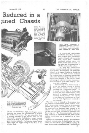
1.7i ins. To restrict engine depth, a rectangular-section induction pipe is used and is secured close to the wide but shallow valve covers. The gear case at the front is specially designed for the pancake unit, and the transversely mounted fuel-injection pump, attached direct to the front of the engine, is driven by bevel gears from the canishaft. Fuel-injection pipes of almost equal length are clipped along the top face of the cylinder block. .A drop-forged case-hardened camshaft is driven from the crankshaft by helical gears, and hydraulic tappets with push-rods operate the valve rocker gear. Chromiumnickel-steel exhaust valves with Ste]lite-covered seats are used, and the guides are chromium-plated to afford a more durable surface.
All main and connecting-rod bearings are steel-backed and lead-bronze precision-finished, the connecting rods being split obliquely at the big-end for removal through the cylinder block. The shaft is Tocco hardened. The crankcase base, an aluminium casting which is finned for effective cooling, is.divided into two compartments forming a wet and dry sump. Lubricating oil is drawn from the dry compartment anti supplied to the other sump by a geartype return oil pump.
All lubricating oil is drawn through a screen and pumped through a full-flow filter, which is mounted on the sump and equipped with a replaceable element. Oil is passed from the filter to the bearings, gudgeon pins, valve mechanism and timing gears, all of which are supplied through internally drilled passages. The capacity of the engine lubrication system is 5-1. gallons, of which 4 gallons are contained in the wet sump.
The water pump is attached to the crankcase base and driven by a single belt and pulleys from the crankshaft. An extension from the front of the crankshaft operates the dynamo, air compressor and fan. The fan is enclosed in a sheet-steel shield attached to the radiator. The radiator, mounted ahead of the front axle, has shutters which are manually controlled from the driving seat. The thermostat, together with most other accessories, is separated from the power unit to facilitate maintenance and is mounted on a frame outrigger.
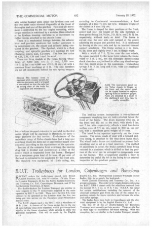
Contrary to contemporary practice, the preselective gearbox is attached to the flywheel housing and is suspended as a unit with the engine and fluid coupling. In effect, the mounting arrangements form a parallelogram with rubber-bonded units under the flywheel case and the two other units situated diagonally at the front of the engine and rear of the gearbox Fore-and-aft movement is controlled by the rear engine mounting, whilst torque reaction is restrained by a snubber blade attached at the flywheel housing, restricted in its movement by rubber blocks attached to the chassis frame.
There is a mechanical linkage between the selector lever and gearbox quadrant, but busbar operation is by compressed air, the piston and cylinder being contained in the gearbox. The flywheel, which is a fluid coupling, and epicyclic gearbox are supplied by Self Changing Gears, Ltd., Coventry. The box has ratios of 4.15, 2.36,1.56 and I-to-1 forward.
There are three models in the range, having wheel
bases of 5,000 'mm. (16 ft. 5 ins.), 5,500 mm. I18 ft. 01 ins and 6,000 mm. (19 ft. 81 ins.), all with a common front overhang of 8 ft. The side members are cut off immediately behind the rear spring hangers,
but a bolt-on dropped extension is provided on the first series, which will be operated in Denmark, to carry a large platform for bus service. Predecessors of the underfloor range of Volvo chassis have had a long rear overhang which has been cut to appropriate length after assembly, according to the requirements of the operator.
Because of the extensive front overhang, the steering drag link is divided and incorporates a. relay at the centre which is suspended from the frame. Designed for a maximum gross load of 14 tons, 43 per cent. of the load is estimated to be supported by the front axle. The standard tyre equipment, of 12-ply rating, has,
according to Continental recommendations, a load capacity of 2 tons 7A cwt. per tyre. Unladen weight of the chassis is 4 tons 181 cwt.
The frame is shaped for door positions at the front, centre and rear, the height of the side members at
these points being 2 ft. 9.1 ins., 3 ft. 01 in. and 2 ft. 911 ins.
respectively, without body ,or load. The frame is curved over the rear axle and ramped at the centre adjoining the engine and gearbox bay. It is reinforced by boxing at the rear axle and by an-internal channel support amidships. The frame section is f in. thick, 9f ins, deep and slightly over 3 ins, in flange width.
With a width of 7 ft. 71 ins. over the rear wheels, the space occupied by the large tyres reduces the frame width to 3 ft. 2 ins., but the telescopic double-acting shock absorbers are„,inclined to offset any disadvantage that this might cause in the suspension. Underslung springs 5 ft. 3 ins, long and 4 ins, wide are employed at both axles.
The braking system incorporates a two-cylindered compressor supplying two air tanks attached below the front of the frame. The drum diameter (16f ins, at the front and 15f ins, at the rear), with shoes 5 ins. and 7 ins, wide respectively, affords a total foot-brake surface area of 571 sq. ins., equal to 40.8 sq. ins, per ton; with a maximum gross weight of 14 tons.
The hand brake operates separately on the transmission. The drum, made of steel with a bonded castiron lining, is attached to the final-drive input shaft_ The wheel brake drums are reinforced to prevent bellmouthing and to act as a heat reservoir. The method of adjustment is novel, the brake camshaft lever being retained in a quadrant which is drilled so that the posi tion of the lever can be arranged to compensate wear on the facings. This arrangement enables a fitter to determine the useful life left in the facing by an external inspection of the quadrant position.