


Saving Space on Trolleybuses
Page 62
If you've noticed an error in this article please click here to report it so we can fix it.
A Resume of Patent Specifications that have Recently been Published
AN improved layout for a trolIeybus chassis is shown in patent No. 420,510 (void) by A. Dewandre, of Liege, Belgium, and G. Lienhard, 6, rue Leon Vaudoyer, Paris. The object of the invention is to mount the entiie driving mechanism under the driver's seat, thus leaving the rest of the vehicle uncomplicated by transmission obstructions.
In the drawing it will be seen that the electric motor (1) drives, through the medium of a clutch (2), a bevel gear (3), which drives the individual axle shafts after a further spur-gear reduction. Each road wheel is, of course, pivoted for steering, and independently linked to the chassis, a common transverse spring being provided for suspension.
The inventors claim that this design permits not only extra space being allotted to the body, but improves the stability and road-holding properties.
Parcelcar Chassis Improvements.
AN unusual design of chassis for light three-wheeled vehicles, such as parcelcars, is described in patent No. 419,984, by j. Haynes, 20 Darnley Street, Brooks's Bar, Manchester, and H. Arrowsmith, 28, Leighton Street, Moston, Manchester. This design is specially applicable to vehicles driving on a single front wheel. Hitherto, it has been the practice to mount the engine on the front fork, which is, the inventors state, the weak point in an arrangement of this kind.
The present improvement lies principally in the front-wheel construction, which consists of a universal joint (4) on the axle, transmitting both driving and braking forces to the wheel, whilst the other end of the axle runs in a bearing slidably mounted on a quadrant (7), which permits of steering movement. Springing is arranged for by pivoting the secondary frame '(3) on the shaft (2), springs (6) being interposed at the front end. The engine and gearbox are mounted on the cross girder (1), the drive being taken by a chain to a sprocket (5) formed on the brake drum.
This system of construction is clearly more capable of withstanding stresses in all directions than is a fork.
B48 tion describes a design in which the oil is supplied to the working space of the cylinder through passages other than those used for the spill discharge. Referring to the drawing, the oil reaches the compression space from the supply line (1) via the passages (3) and the annulus (2), passing thence through cross-holes in the plunger and flowing up through the central bore '(shown in dotted lines) into the working space. • The spill discharge takes place from the helical groove into a separate annulus and passages, illustrated in the drawing above those previously described, se that the flow of liquid is not at any time reversed. In addition, the central-bore feed to the workingspace is claimed to avoid eddies in the fuel.
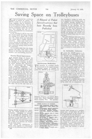
An Anti-backfire Carburetter.
IN patent No. 420,609 appears a delscription of a carburetter in which the throttle valve is time-controlled, the patentees being C. Brown, 19, Trinity Road, Birchfield, Birmingham, and Arm!, Ltd., Holford Works, Perry Barre Birmingham. The object of the invention is to ensure that the throttlevalve cannot be "slammed open," an action which usually causes backfiring and other unpleasnt results due to the momentarily incorrect mixture. This is achieved by anchoring the throttle control (2) to a piston (3) working in a cylinder formed in the body of the carburetter. This cylinder is open at the bottom (via a restricting orifice) to the petrol in the float-cha.mber.
The result of a sudden full-throttle movement by the driver is that the spring joint (1) is compressed, the throttle itself opening at a predetermined rate. A ball valve (4) allows free entry of petrol to the cylinder, so as not to limit the shut-off speed.
A further advantage claimed is that the petrol expelled from the cylinder during acceleration raises the level in the float chamber for a few seconds ; this results in a desirable momentary enrichment, which compensates for the reduction of suction on the jet as occurs when the throttle is quickly opened.