


OVERHAULING THE MAUDSLAY.
Page 21
Page 22
Page 23
Page 24
If you've noticed an error in this article please click here to report it so we can fix it.
No. 6.—Hints on Handling the 4 and 5 ton Chassis—How to Take Down the Overheadvalve Engine—Helpful " Gadgets " Which the Makers Use—Short Cuts and Kinks.
THE MAJORITY of Maudslay vehicles in use is of the 4 and 6 ton type, and, as in their main features these chassis are very similar in construction, the following notes may be taken as
applicable to either type. . --' • Uncommon as is the overhead-valved type of. engine on commercial vehicles, it is one which possesses certain constructional advantages, apart from the greater Volumetric efficiency which this form of valve arrangement is generally admitted to secure. The design of the Maudslay engine is such that many of the engine parts are more than usually accessible. It is possible very easily to dismantle the valveoperating gear and valves, and the connecting rods and pistons are easily removable through the doers which are fitted to each side of the crankcase.
. • At first glance, the valve accessibility appears to . be hindered by the presence of the overhead camshaft and its casing, but such is not really the case.
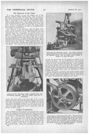
In order to permit the removal of the valves and the cases in which they are carried, all that is necessary is to undo the bolts which hold down the camshaft easing on the near side of the cylinder head, when the casing with the camshaft still in position can be swung over to the off side, the pin joints, on that side acting as a hinge: Before this is done, however, it is essential to get the universal joint at the top of the vertical driving shaft into the correct position to permit the movement to take place. This is achieved by rotating the crankshaft until the slots in the phosphor-bronze universal joint ball are parallel to, or at right angles with, the horizontal centre line of the engine. It should he noted that the engine must on no account be cranked except when the camshaft casing is in its working position, otherwise., serious damage may be done..
With the easing thrown over, the valve boxes and the valves complete with their springs can be removed together, alter screwing out the gun-metal nuts which hold them in place. A special spanner will be found in the kit for this purpose.
Stripping the Chassis.
As, however, we are presuming that readers will wish to undertake a complete chassis overhaul, we will first outline briefly, as we have done in other cases, the. most convenient sequence of dismantling operations. It is preferable, as usual, to start at the front of the chassis and work backwards, removing.
first the bonnet and the stay which holds the radiator to the dash and the hose connections, to the engine. The removal of the caps from the trunnion supporting brackets then allows the radiator to come off. AS the pump, in the Mandalay design, is carried on the radiator, the removal of the Whittle belt which drives it must not be overlooked. The starting handle andits bracket should now be removed.
The next job is to take off the chain case which houses the magneto driving chain, in order to give room for the enRine to be shifted forward slightly to allow of its removal. This chain case can be removed complete with the bracket which carries it at the lower end. • There istno need to separate the two. After that the magneto driving chain, the magneto, and its bracket, which 'latter ia bolted to the main frame,. should come -off. The next unit to dismount is the steering box. The controls -should first be uncoupled.. Then the bolts which hold the flange on the lower end of the column to the heir should be undone, also these which hold the column to the dash, when the latter can be removed.
Before the steering •box can come out the steering drop arm must be taken off. The side steering rod will swing sufficiently to enable this to be done with-. out uncoupling the hall joint by which iLis attached to the lower end of the drop arm. It should be noted that the latter is held on a taper, and a " puller" for the purpose may be necessary. The removal of the bracket bolts will now enable the box to be taken off. Next, the clutch atop must come off, and then the bolts, which hold the coupling muffs in position on the long clutch shaft. The muffs at either end can then be slipped along the shalt and the latter removed.
The Removal of the Units. .
It is now possible to get the engine out of the chassis without taking off the dash. The oil pipe to the dash tell-tale. must, of course, first be uncoupled, also the petrol pipes and-controls. The exhaust manifold is connected to its pipe by an expansion joint, which simply slips apart. The engine must be tilted and swung forward to allow the flywheel to clear the dash, and it is preferable to plane the sling round the rear -pair of cylinders in order to counterbalance the -weight of the flywheel.
The removal of the gearbox calls for little comment. First uncouple the change-speed slide bars by removing the pins-from them. The change speed and selector gear can, meanwhile be left in position if desired. Then take off the hemispherical universal joint cover behind the foot brake drum, slip it hack on the propeller shaft, and remove the two outside universal joint pins. Unship all the foot brake ,gear, .including the two brake-shoe supporting strips, which extend across the chassis. The propeller shaft can now be taken down and the side brake operating rods uncoupled. The removal of the spring pins will then
enable the rear axle, to be run back on its wheels, when the frame has been properly supported, and the front axle can similarly be removed. When the frame has been completely stripped, it. will be as well to examine it carefully all over, and to ensure that all nuts are tight, esnecially those which are held by. spring washers only.
Engine Peculiarities.
The method of removing the valves and valve boxes from the cylinder heads has already been described, and the grinding in of the valves is a simple matter. it should be remembered, however: that the valve boxes also rest on face joints in the cylinder heads, and occasionally it may be found that these also need-grinding in. In such cases it is necessary to tap the small locating dowel peg flush with the circular portion of the box, so that the latter can be rotated freely. When the grinding has been corn
B18
pleted, the dowel peg can be tapped out again to its original position. if, on examination, the exhaust valves are found to be badly burned, it is practically certain. to have occurred through the valves sticking up in their guides, due to oil from the camshaft case having found its way on to the valve stone. This could have been prevented if the precaution had been taken, after each day's run, of squirting a little
paraffin on them. ,
Before lifting the cylinders., the small bracket which holds the vertical driving shaft must be cast loose. The camshaft easing can either be left in position or be taken off before the cylinders are raised. As regard cylinder wear, it should be noted that the Mandalay Co. stock an oversize piston for replacement purposes. This is 10-1,000ths of an inch larger than standard, and, in the event of the wear being such as to make regrinding of the cylinder bores desirable, it is advisable to grind them out te this dimension.
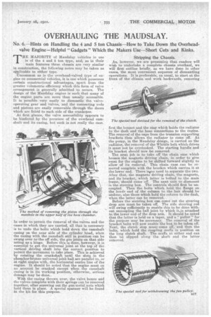
A little difficulty may perhaps be • experienced in removing the magneto pinion together with the starting dog and twin, belt pulleys from the crank-shaft, if a proper tool is not a`vailable. The Maudslay Co. have a useful device for this job, which we are able to illustrate. It consists, as will be seen, of a recessed block, suitably drilled and tapped, which has an internal toothed ring which can be slipped overthe magneto pinion teeth. It is then twisted round so that a purchase is obtained on the back of the pinion teeth, and the • screw inserted in the tapped hole is tightened .up against the endof the crankshaft. In this way the pinion and pulleys can be drawn off. The magneto chain adjustment must bo made when the engine is in position in the chassis by sliding the magneto bracket in the V slots by which it is held.
For checking the adjustment of the valve tippet clearances, the MaudslaT, .Co. provide a " go " and " not go gauge, in the form of a folding rule, in 'every tool kit. This should be used when the tappet roller is on the idle part of the cam. Care must be taken to ensure that the tappet screws are quite tight, as if they become loosened the valves. may be held up and damaged by burning.
A Clutch Precaution.
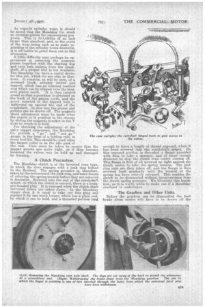
The Maudslay clutch is of the inverted cone type, in which the cone engages with a junk ring bolted to the flywheel. The spring pressure is therefore, taken by the nuts a rou.nd the junk ring, arid 'some Means of relieving the spring tension before they are removed is desirable. Screwed into the end of the crankshaft spigot, an which the clutch is carried, there is a hexagon-headed plug. It is exposed when the clutch shaft universal joints are taken down, • In-the Maudslay repair shop it is usual to take out this plug and _ replace it by one Much longer, which has a plain end; by which it can be held, and a threaded portion long
enough to leave a length of thread exposed, when it has been .screwed into the crankshaft spigot. On this exposed portion is threaded a flange provided with flats, to take a spanner, and of large enough diameter to stop the clutch cone centre coming off. This flange is first of all screwed up tight against the clutch centre to take the spring tension. The junk ring nuts are then taken off' and the flange is then screwed' back gradually until the tension of the spring has been entirely released. This enables the clutch to be gjamantled -without inconvenience froth the clutch spring pressure. We illustrate this handy tool, as it is worth while to make one if a .Maudslay overhaul is undertaken..
The Gearbox and Other Units.
Before the gearbox can be dismantled the foot brake drum centre will have to be drawn off the tapered end of the main shaft. The best Way to do this is to have a piece of stout square 'section bar, of a length which will fit between the universal joint
pin bos.s'es in the brake drum • centre. The ends should be tapped to receive the threaded ends of two pins. which fit in the universal joint pin holes, and there should be a tapped hole through the centre of it, through which a screw can be passed to press against the end of the main shaft. The universal joint flange on the end of the first reduction Pinion can be slipped off its castellations when the
which passes through the boss to hold it, has been driven out. The striking forks similarly are pinned to the sliding rods, which can be slipped through them and withdrawn from the box, after the pins have been driven out. The -packing of these rods to prevent oil leakage must not be overlooked when re-assembling. The design of the Maudslay rear axle makeS it a
particularly accessible Unit. When in Position on the chassis, the removal of the lower half of the axle centre enables the condition of the main spur gear wheel to be inspected. By removing, the hub caps and withdrawing the axle shafts; the whole of the 'rear axle and differential gearing can be lifted from the axle forging complete in its housing, as shown in ono of the photographs reproduced on a previous page. The crown wheel Call be taken out by removing the caps at each end of its shaft, and taking off the nuts and driving it out, but care must be taken not to damage the wheel in so doing. The, bevel pinion can he withdrawn with its bearings by withdrawing the rear bearing housing. The rear brake shoes+ are of rather a peculiar • pattern, and care must he taken whenreplacing the small section of lining that they are of a thickness which stands well-proud of the metal of the shoes.