


Patents Completed.
Page 22
If you've noticed an error in this article please click here to report it so we can fix it.
Complete specifications of the following patents will be sent to any address in the United Kingdom upon receipt of eightpence per copy at the Sale Branch, Patent Office, Holborn, W.C.
Timing a Magneto.
H. Diehl.—No. 24,697/11, dated under International Convention, 26th November, 1910.—This invention relates to the automatic control of the timing in magneto-ignition apparatus; such timing is dependent on the angular position of the magneto shaft in respect to the motor
shaft or a shaft driven therefrom. An element which is flexible in itself and is also subject to centrifugal force is used to connect the two shafts. In the construction illustrated a chain of heavy links is used. While running at low speeds, this chain hangs closely round the inner member and the end at which it is connected to the respective driven and driving members overlaps. When the speed rises however, the effect of centrifugal force on the chain causes it to lie against the upper member and thereby to displace the ends relatively owing to the greater circumference which it. is allowed to occupy. In this way a very considerable angular displacement may readily be obtained.
Renault Valve Arrangement.
Louis Renault.—No. 15,907/1911, dateil under International Convention, 12th October, 1910.—Patent of Addition to No. 15,825/11. This specification describes a modification of the arrangement described in patent specification No. 15,825/11. The cylinder surrounded by a cooling jacket is cast integral with the cylinder head, and a suction valve of large diameter is situated in the upper part of the cylinder head. An annular space round the cylinder communicates with the exhaust and is controlled by a sleeve valve working in the cylinder. The upper edge of this sleeve valve is coned inwardly and rests on a bevel seating. The sleeve valve may have an an
nular shoulder formed on it, so that the pressure inside the cylinder holds the valve tight on its seating. The advantages of this construction are stated to be that the assembling of the engine is faci litated, the exhaust is practically instantaneous and a tight seating of the exhaust valve is obtained.
Carburetter Improvements.
Jas. Stothart Pearson and Fred. Stothart Pearson.—No. 18,703, dated 19th August, 1911.—This carburetter is suitable for use with petrol or petroleum and is intended primarily for making a n:ixture suitable fur welding or brazing materials or where very-high temperatures are desired. A cylindrical vessel is divided into two compartments, the upper one of which is the storage vessel for petrol, petroleum, or other liquid. In the lower vessel two aiesupnly tubes are arranged, the one at the bottom consists of a straight supply main with lateral branches, these being pierced with very small holes on their underside, the other air pipe is arranged circumferentially about half-way up and is similarly provided with holes. Both these air pipes are supplied through a, common main, suitable stop-cocks allowing either or both to be used. This lower compartment is divided into two parts that are separated by an air-tight partition through which short lengths of tube are passed. On the ends of these tubes are fixed downwardly-depending gauze tubes filled with cotton-wick or other absorbent. The incoming air passes through a layer of liquid and then through the cotton-wick and out at the connecting tubes into the gas chamber. A final mixing is then obtained by passing it through a gauze diaphragm on its way to the outlet pipe. Suitable feed pipes for the liquid are provided.
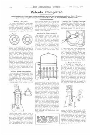
Facilities for Cylinder Cleaning.
Reginald Walter Maudslay and Thu Standard Motor Co., Ltd.—No. 16,805, dated 1st July, 1911,—This invention consists in the provision of such an opening in the cylinder wall that the interior of the cylinder, the valve passages and the piston head may be inspected and cleaned by tools passed through the opening. The side of this sight passage next to the combustion chamber is opened out, so that the sides of the passage are approximately tangential to the cylinder bore. The opening is conveniently used for the insertion of the sparking plug. The illustration shows the method of use.
An Argyll Valve Gear.
J. S. Matthew, H. Perrot and J. M. Rubury.—No. 29,947, dated 24th December, 1910.—A gear for operating a sleeve valve is described in this specification. Is consists of an eccentric mounted obliquely on a half-speed shaft, and having its strap coupled by a ball-andsocket joint to the lower end of the sleeve valve. The eccentric disc is preferably circular, and formed with the usual groove to accommodate the strap or collar, which for convenience in assembling is preferably made in two parts. An outwardly-projecting lug formed on the strap or collar is provided with a
socket, in which is engaged a ball rigidly attached by a stud to the sleeve valve as shown in the accompanying illustration. Adjustment for wear is obtained by screwing down a plug which bears on the upper part of the ball. The eccentric disc may be formed with a number of holes, through any one of which the shaft may be passed, thereby allowing considerable variation of the setting of the valve mechanism.