


A Double-acting Engine
Page 54
If you've noticed an error in this article please click here to report it so we can fix it.
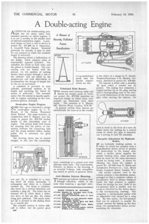
ALTHOUGH the double-acting principle has for many years been standard practice in steam engines, it is as yet a novelty in the smaller sizes of internal-combustion engine. A practical design for such a unit is shown in patent No. 977,609 by S. Opperrnan, 5, Greenhill Park, Barnet. Intended primarily for aircraft, it may be used for any purpose in which the available height is restricted.
The drawing shows a half-section of the design, which employs pairs of horizontally opposed cylinders. The cylinders are closed at both ends, and the piston is double-headed. The connecting rods are linked with the pistons, via the medium of rocking beams; these project through a slot in the cylinder, and are fitted at the gudgeon-pin end with slide-blocks to accommodate the change of length due to the arc of movement.
A camshaft is provided to each cylinder, positioned midway in its length and operating the valves by means of push-rods. The inventor states that the scheme is equally applicable to engines operating on the compression-ignition principle.
Swash-plate Engine Progress.
SOME time ago we described a design of awash-plate engine by C. G. Nevatt, of the Haven, Waterford Road, Bristol. The same inventor, in conjunction with F. Shearer, now discloses in patent No. 477,716 further details of this interesting type of engine. This patent deals with means for ensuring that the points of con: nection between the connecting rods and the swash member follow similar paths; this is necessary for good balance.
The drawing shows one of several designs; in this case the connecting rod end (2) is attached to a bearing block (5) which, externally, is rectangular and slides in a channel member (6). The block is cylindrically bored (in a vertical direction) and contains a plug (3). The latter has an internal slot in which block 1 slides; two faces of this are flat, the others being part spherical. The swath member (4) is pivoted to the sliding block by a central pin. The complex motion is rather difficult to follow, but the patent gives g44 Fabricated Body Bearers.
"THE bearers used between body and I chassis are usually made of wood, but patent No. 477,551 describes an improved design in which these components are fabricated from sheet
metal. The patentee is S. Blanch, 847, Harrow Road, London, N.W.10. In general outline these bearers are substantially the same as in the wooden type, consisting of a central arch with upswept outer ends. The cross-section, however, as shown in the drawing, is an inverted V-shape, with strengthening inserts at points of greatest stress.
Anti-vibration Injector Mounting.
prevent an injector working loose through vibration, whilst at the same time ensuring a gas-tight joint, is the object of a design by F. Deckel, Waakirchnerstrasse 7-13, Munich, Germany, described in patent No. 978,052. The injector is fitted with a shoulder (2) upon which a tubular nut (9) presses. The sealing face comprises a conical portion (3) on the plug, mating with a corresponding cone in the bore. To avoid disturbance of the fuel-supply pipe when moving the injector, the oint is made in the form of a cone (5) which forms the seating for a conical union th which the pipe is. attached, nut 1 serving to lock the assembly.
One-point Adjustment for Hydraulic Brakes.
IN an hydraulic braking system, in I which an initial low pressure from a large-diameter piston serves to present the brake-shoes to the drams, after which a smaller piston supplies the greater braking force, some provision must be made for the extra movement caused by facing wear. A means for effecting this forms the subject of patent No. 977,839 from D. Brock and Automotive Products Co., Ltd., Brock House, Langham Street, London, W.I.
The master cylinder used in the scheme employs a two-diameter piston, arranged so that a constant volume of low-pressure fluid is always displaced before the high pressure is applied. When the facings are new, little of the low-pressure fluid is needed, and the excess is absorbed by the device shown in the accompanying drawing. This comprises a spring-loaded piston with an adjustable stop formed by a wing nut. By this means, the low-pressure fluid can be adjusted to exactly the correct amount for taking up the shoe slack, the spring-loaded piston accommodating.tbe remainder.